
Torsional damper pulley

a technology of damper pulleys and torsional pulleys, which is applied in the field of torsional damper pulleys, can solve the problems of high cost of facilities, lack of general versatility of casting methods, waste of material with a large cutting amount, etc., and achieves the effect of facilitating the manufacture of the pulley body, reducing the number of working process steps and working time, and enhancing the general versatility of the damper pulley

Inactive Publication Date: 2006-02-09
FUKOKU CO LTD
View PDF9 Cites 10 Cited by
  • Summary
  • Abstract
  • Description
  • Claims
  • Application Information

AI Technical Summary

Benefits of technology

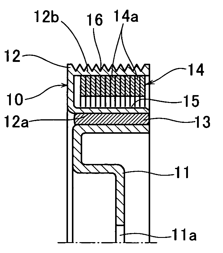
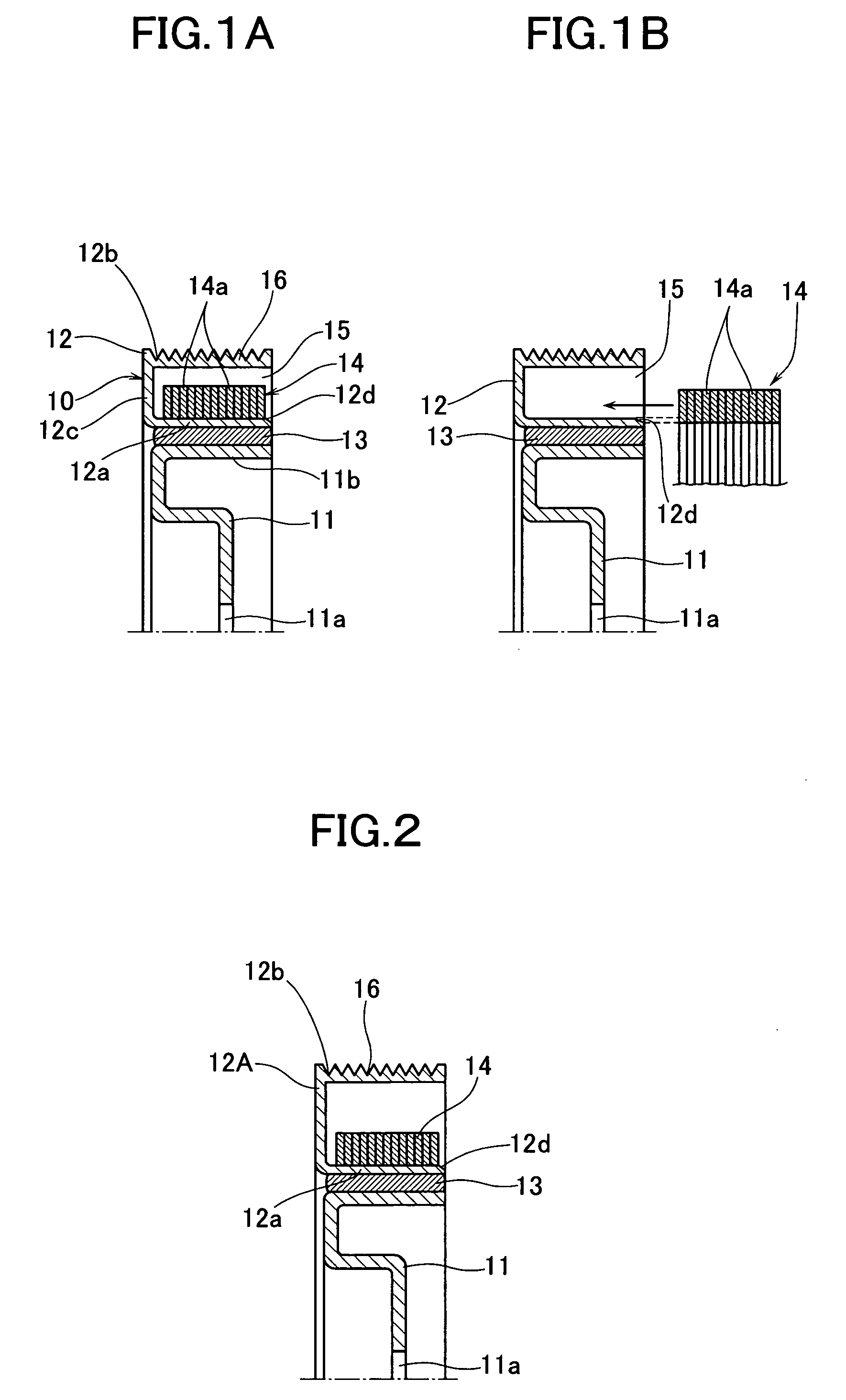
[0010] In the present invention, the pulley body is constructed by the frame having the pulley groove and an inertia mass element attached to the frame, and therefore manufacturing of the pulley body is facilitated. Even if the internal combustion engine is changed to an internal combustion engine with a different vibration characteristic, it can be handled by replacing the inertia mass element corresponding to the vibration characteristic of the internal combustion engine, and therefore general versatility of the damper pulley is enhanced. The frame can be formed by cold forging or pressing work of the plate material, and therefore the number of working process steps and working time can be reduced.
[0011] According to the present invention, it is preferred that the inertia mass element be formed by overlaying a plurality of annular plates on each other and bonding them. Thus, the mass of the inertia mass element can be easily adjusted by increasing and decreasing the number of annular plates to be laminated, increasing and decreasing the specific gravity of the annular plates, and the like. Accordingly, the adjustment of the mass of the inertia mass body corresponding to the vibration characteristic of the internal combustion engine to which the damper pulley is applied can be facilitated, and general versatility of the damper pulley can be further improved. Since all the work for the pulley body and the hub including the inertia mass element can be made only by a press, it is possible to produce the damper pulleys through a production line, and thus the cost of the damper pulleys can be reduced.
[0012] An adhesive can be used for bonding the laminated annular plates, but in order to improve productivity, it is preferred to form the engaging pieces at the annular plates and mechanically bond them by a press. According to the present invention, cut-and-bent pieces are formed on a surface of the annular plate with spaces between them in a circumferential direction, and by overlaying a plurality of annular plates on each other so that the cut-and-bent pieces are overlaid on each other and pressing them, the plurality of annular plates can be bonded. Alternatively, dowels protruded from one surface of the annular plate to the other surface are formed on the annular plate with spaces between them in a circumferential direction, and by overlaying a plurality of annular plates on each other so that the dowels are displaced in the circumferential direction and pressing them, the plurality of annular plates can be bonded. In this case, it is preferred that a convex portion of the dowel is formed to be narrower than a concave portion. Thus, the bite of the convex portion into the surface of the annular plate becomes sharp and biting force increases, and bonding strength of the annular plates to each other is increased. In addition, the shape stability of the obtained inertia mass body is improved.
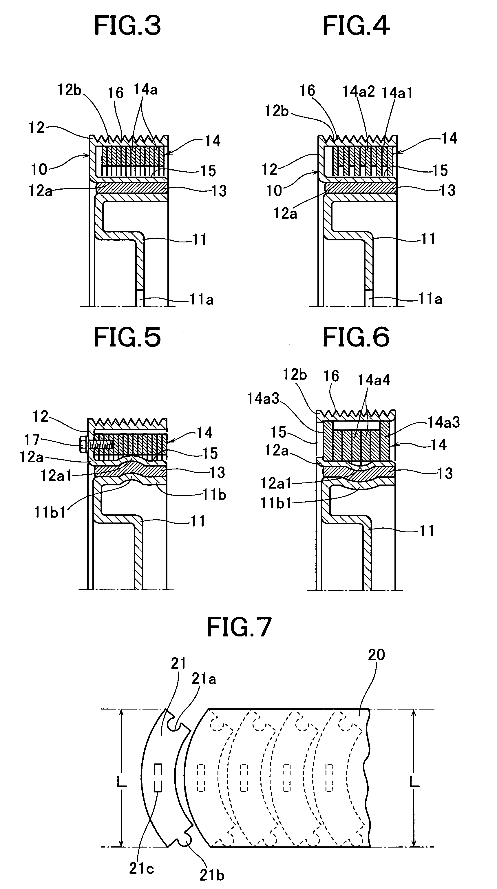
[0013] According to the present invention, it is preferred that the annular plate be formed by joining a plurality of arc-shaped ring pieces in an annular form. The annular plate may be punched out in its entirety by a press, but if a plurality of parts are assembled to form the annular plate, waste of the material can be eliminated. According to the present invention, a plurality of ring pieces are placed in an annular form, and by close-fitting a protruded piece formed at one end of one ring piece of the adjacent ring pieces into a hole formed at a corresponding one end of the other ring piece, a plurality of ring pieces are joined in the annular form. In this case, a concave portion can be formed at least at one side of a base portion of the protruded piece of the ring piece, and a protruded portion fitted in the concave portion is formed at a corresponding side of an open end of the hole. Thus, even if the hole is pressed to expand by the protruded piece on press-fitting of the protruded piece and the hole, deformation is pressed down and absorbed at the fitting portion of the convex portion of the base of the hole and the concave portion of the base of the protruded piece, and therefore the outer portion of the ring piece in the radius direction is securely prevented from opening outward.
[0015] According to the present invention, convex portions outward or inward in a diameter direction may be provided at the same positions in a width direction of the outer circumferential portion of the hub and an inner circumferential wall for defining a concave portion of the pulley body. Thus, the elastic solid can be surely prevented from falling off.

Problems solved by technology

The above-described cutting method requires enormous efforts and causes much waste of material with a large cutting amount.
However, the casting method lacks in general versatility, because if the internal combustion engines to which the damper pulleys are applied are changed, it becomes necessary to prepare a special casting die corresponding to the vibration characteristic of the internal combustion engine.
There also exits the problem of high cost of facilities since the cost of the facilities including the casting die are expensive.

Method used


Image

  • Torsional damper pulley
  • Torsional damper pulley
  • Torsional damper pulley

Examples


embodiment 1

[0039] In the above-described embodiment 1, the inner diameters of all the annular plates 14a constructing the inertia mass element 14 are made smaller than the outer diameter of the inner circumferential wall 12a of the frame 12, and all the annular plates 14a are pressed in contact with the inner surface of the inner circumferential wall 12a, but the inner diameters of some of the annular plates 14a may be made smaller than the outer diameter of the inner circumferential wall 12a and may be pressed in contact therewith.

[0040]FIG. 2 shows another embodiment of the present invention. This embodiment differs in the point that the frame 12 of the pulley body 10 in the damper pulley in FIG. 1 is changed to a frame 12A with the increased outer diameter. For example, the internal combustion engines having the same vibration systems may sometimes require the diameter of the damper pulley to be changed, for example, require an increase in the diameter for the reason of the difference in th...

embodiment 3

[0044] In the above embodiment 3, all the annular plates 14a constructing the inertia mass element 14 is in pressure-contact with the inner surface of the outer circumferential wall 12b of the frame 12, but the outer diameters of some of the annular plates 14a may be made larger and only these annular plates may be in pressure-contact with the inner surface of the outer circumferential wall 12b.

[0045]FIG. 4 shows yet another embodiment of the present invention. In this embodiment, the inertia mass element 14 is formed by alternately laminating first annular plates 14a1 having outer diameters to be in pressure-contact with the inner surface of the outer circumferential wall 12b of the frame 12, and second annular plates 14a2 having such outer diameters and inner diameters to be in pressure-contact with the inner surface of the inner circumferential wall 12a and the inner surface of the outer circumferential wall 12b of the frame 12.

[0046] If such an inertia mass element 14 is press...

embodiment 4

[0047] In the above embodiment 4, the outer diameters of some of the annular plates 14a1 may be made larger to be in pressure-contact only with the inner surface of the outer circumferential wall 12b of the frame 12. The inner diameters of some of the annular plates 14a2 may be made smaller to be in pressure-contact only with the inner surface of the inner circumferential wall 12a of the frame 12. The annular plates 14a2 do not necessarily have to be pressed in contact with the inner surface of the outer circumferential wall 12b of the frame 12.

[0048]FIG. 5 shows still another embodiment of the present invention. In this embodiment, convex portions 11b1 and 12a1 outward in their respective diameter directions are placed at the same positions in the width direction of the annular fixing portion 11b of the hub 11 and the inner circumferential wall 12a of the frame 12. The convex portions 11b1 and 12a1 may be placed at a plurality of spots along the circumferential direction. The conve...


PUM


Abstract

A torsional damper pulley improved in general versatility, easily produced and capable of reduction in production cost. The torsional damper pulley is constructed of a hub 11 fixed at a revolving shaft of an internal combustion engine, an annular pulley body 10 coaxially placed at an annular fixing portion 11b at an outer circumference of the hub, and an elastic solid 13 interposed between an outer circumferential surface of an annular fixing portion and an inner circumferential surface of the pulley body. The pulley body 10 is constructed of an annular frame 12 substantially U-shaped in section, having an concave portion 15 open at one side in an axial direction, and an inertia mass element 14 inserted into the concave portion 15 in an axial direction and fixed. The inertia mass element is a laminate made by overlaying annular plates 14a on each other and bonding them, and the inertia mass element is fixed by being press-fitted into the concave portion.

Description

TECHNICAL FIELD [0001] The present invention relates to a torsional damper pulley mounted on a revolving shaft of an internal combustion engine such as an engine of an automobile. BACKGROUND ART [0002] A pulley taking power for belt-driving of a radiator fan or the like from a crankshaft of an internal combustion engine is formed to be a torsional damper with an elastic solid being incorporated in it to absorb a torsional vibration of the crankshaft, and with an inertia mass in a pulley body. [0003] As shown in FIG. 11, the torsional damper pulley is constructed of a hub 2 fixed to a crankshaft 1 of an internal combustion engine, an annular pulley body 3 coaxially placed outside the hub 2 in its diameter direction, and an elastic solid 4 interposed between an outer circumferential surface of an annular fixing portion 2a of the hub 2 and an inner circumferential surface of the pulley body 3. A pulley groove 3a in a suitable shape corresponding to a shape of a surface of a driving bel...

Claims


Application Information

Patent Timeline
IPC IPC(8): F16H55/36F16H55/49F16F15/12F16F15/126F16F15/31F16F15/315
CPCF16F15/126F16H2055/366F16F15/3153F16F15/31
Inventor WATANABE, HIDEAKIOHKI, KAZUMIYOSHIDA, TAKASHIISONO, MASAKAZU
Owner FUKOKU CO LTD
Learn More