Imaging lens
a compact, lens technology, applied in the field of compact imaging lenses, can solve the problems of difficult to reduce shorten the total length of the lens system, and difficult to keep the angle of emergence small, and achieve the effect of superior optical characteristics
- Summary
- Abstract
- Description
- Claims
- Application Information
AI Technical Summary
Benefits of technology
Problems solved by technology
Method used
Image
Examples
first embodiment
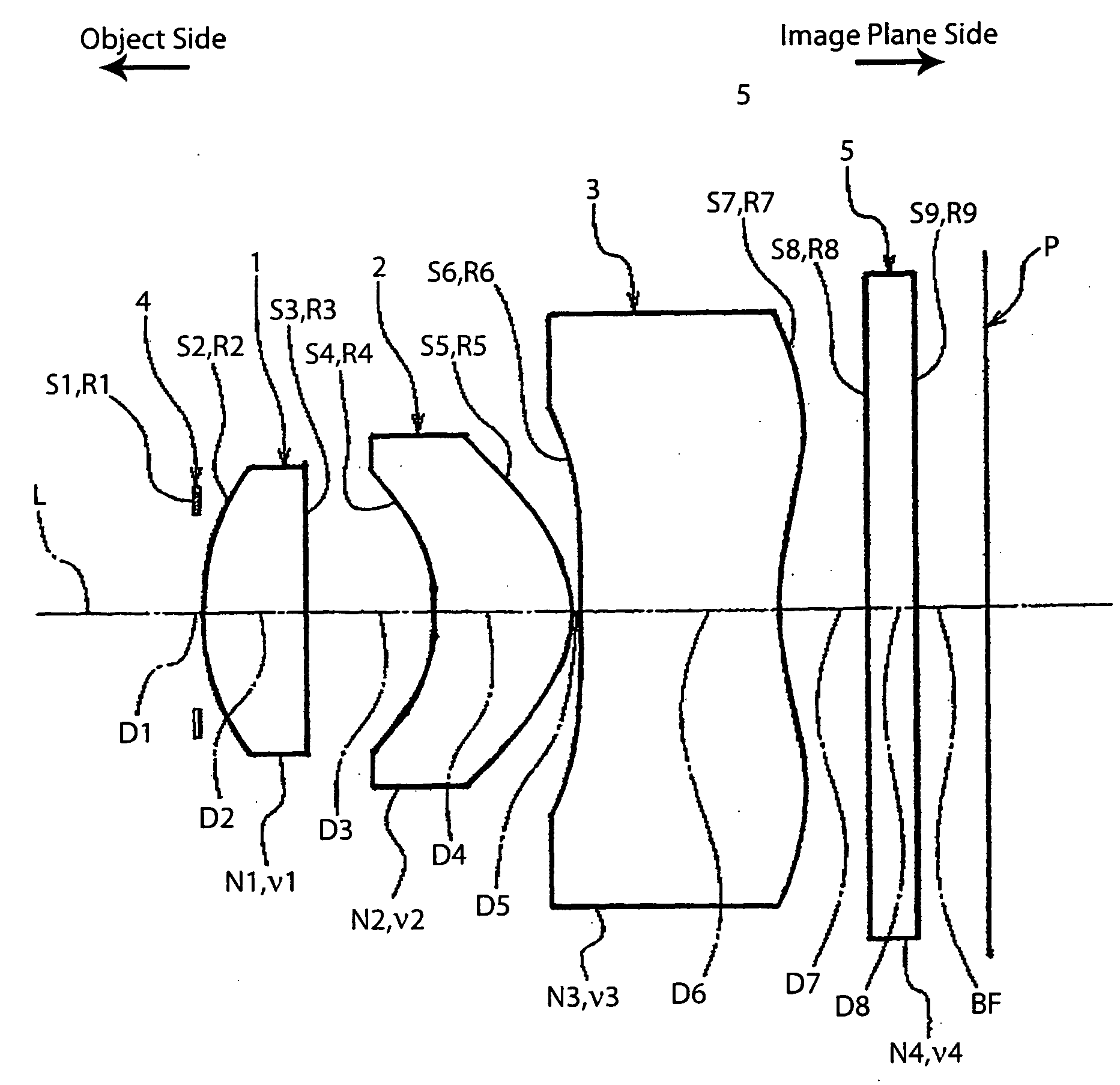
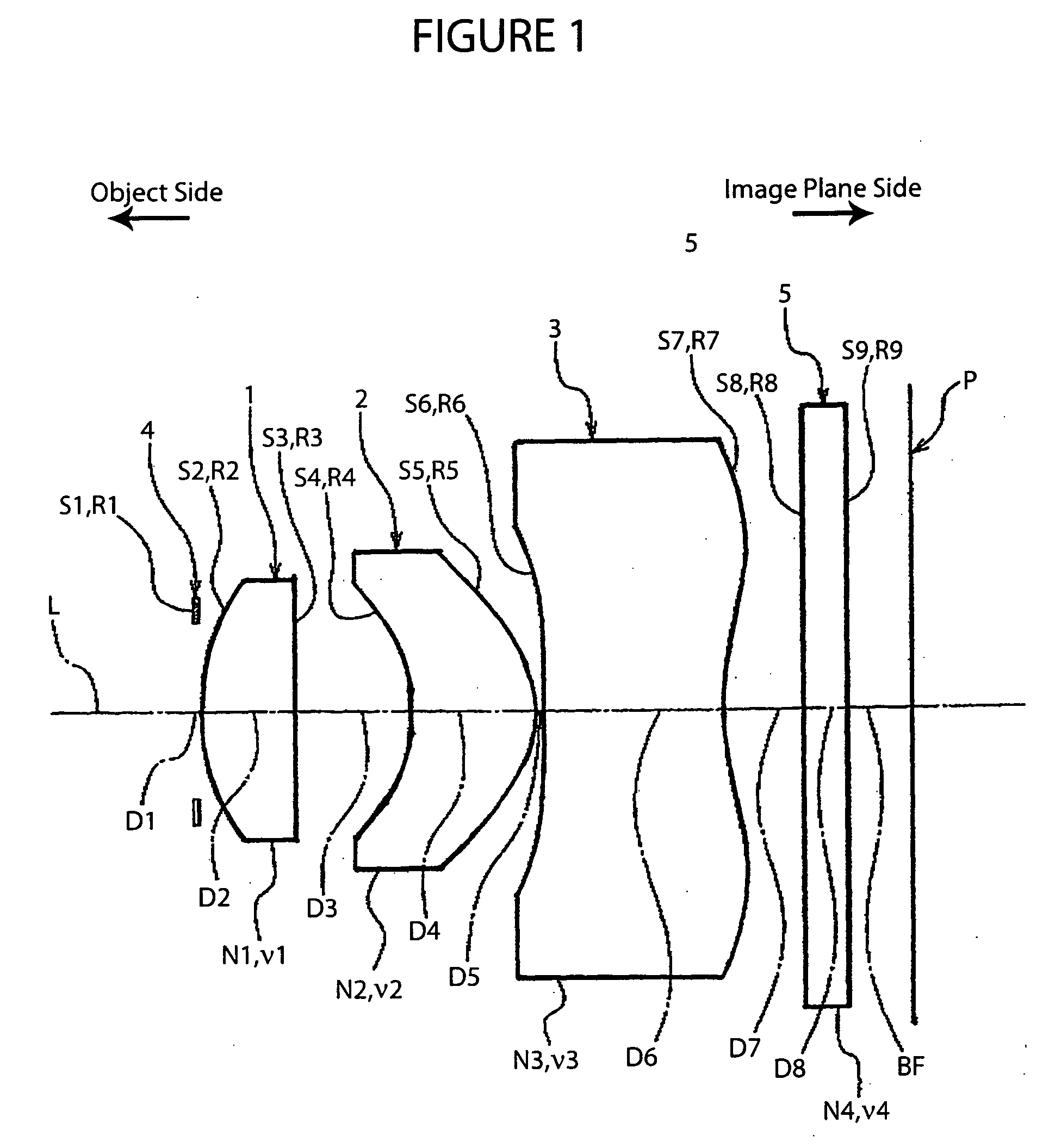
[0037]FIG. 1 shows the basic structure of a lens system according to the imaging lens of the present invention.
[0038] As shown in FIG. 1, this imaging lens includes the following elements along an optical axis L, going from the object side to the image plane side: an aperture stop 4 having a predetermined diameter, a first lens 1 with a convex surface facing toward the object side having an overall positive refractive power, a second lens 2 with a concave surface facing toward the object side having an overall positive refractive power, and a third lens 3 with a concave surface facing toward the object side having an overall negative refractive power. Also, in the arrangement described above, a glass filter 5, e.g., an infrared cut filter or a low-pass filter, is disposed behind the third lens 3, and an image plane P, e.g., a CCD, is disposed behind that.
[0039] More specifically, the imaging lens is formed with a three-group, three-lens structure, with the first lens group formed b...
second embodiment
[0066]FIG. 3 shows the basic structure of a lens system according to the Table 4 shows the main specifications. Table 5 shows various numerical data (settings). Table 6 shows numerical data relating to the aspherical surfaces. In this working example, the numerical data for the conditions (1)-(6) are as follows:
TL / f=7.648 / 5.83=1.31; (1)
v1=70.2, v2=56.4, v3=30.3; (2)
|R4| / |R5|=1.54; (3)
|R6| / |R7|=7.79; (4)
D5 / f=0.017; and (5)
D4 / D6=0.70. (6)
TABLE 4Focal Length f5.83Total Length TL of Lens System7.648(mm)(air conversion distance usedfor D8 (glass filter 5))(mm)F Number2.89Back Focus1.83(FNo.)(Air Conversion)(mm)Field Angle63.4°Object Distanceinfinity (∞)(2ω)
[0067]
TABLE 5Curvature RadiusDistanceIndex of RefractionAbbeSurface(mm)(mm)(d line)NumberS1R1∞Aperture StopD10.000S2R22.701D21.050N1ν1S3R359.2211.4874970.2D31.278S4*R4−2.150D41.394N2ν2S5*R5−1.3961.5091456.4D50.100S6*R6−22.638D61.996N3ν3S7*R72.9061.5838530.3D70.850S8R8∞D80.500N4ν4S9R9∞1.5168064.2BF0.650
*aspherical surface
[...
third embodiment
[0070]FIG. 5 shows the basic structure of a lens system according to the Table 7 shows the main specifications. Table 8 shows various numerical data (settings). Table 9 shows numerical data relating to the aspherical surfaces.
[0071] In this embodiment, the numerical data for the conditions (1)-(6) are as follows:
TL / f=7.62 / 5.78=1.32; (1)
v1=70.2, v2=56.4, v3=30.3; (2)
|R4| / |R5|=1.53; (3)
|R6| / |R7|=9.13; (4)
D5 / f=0.017; and (5)
D4 / D6=0.71. (6)
TABLE 7Focal Length f5.78Total Length TL of Lens System7.620(mm)(air conversion distance usedfor D8 (glass filter 5))(mm)F Number2.89Back Focus1.85(FNo.)(Air Conversion)(mm)Field Angle64.1°Object Distanceinfinity (∞)(2ω)
[0072]
TABLE 8Curvature RadiusDistanceIndex of RefractionAbbeSurface(mm)(mm)(d line)NumberS1R1∞Aperture StopD10.000S2R22.707D21.050N1ν1S3R366.6311.4874970.2D31.229S4*R4−2.141D41.407N2ν2S5*R5−1.3961.5091456.4D50.100S6*R6−26.318D61.984N3ν3S7*R72.8831.5838530.3D70.850S8R8∞D80.500N4ν4S9R9∞1.5168064.2BF0.670
*aspherical surface ...
PUM
 Abstract
Description
Claims
Application Information
 - R&D
- Intellectual Property
- Life Sciences
- Materials
- Tech Scout
- Unparalleled Data Quality
- Higher Quality Content
- 60% Fewer Hallucinations
Browse by: Latest US Patents, China's latest patents, Technical Efficacy Thesaurus, Application Domain, Technology Topic, Popular Technical Reports.
© 2025 PatSnap. All rights reserved.Legal|Privacy policy|Modern Slavery Act Transparency Statement|Sitemap|About US| Contact US: help@patsnap.com


