Eureka AIR delivers breakthrough ideas for toughest innovation challenges, trusted by R&D personnel around the world.

Drawing apparatus and drawing method

a drawing apparatus and drawing method technology, applied in the field of drawing apparatus and drawing method, can solve the problems of small possibility of serious failure to have a serious effect on the final exposure result, difficult to strictly satisfy these design requirements, and inability to generate and store bitmap data prior to drawing, etc., to achieve stable drawing operation, high resolution performance, and the effect of improving the quality of the final exposur

Active Publication Date: 2006-02-02
SHINKO ELECTRIC IND CO LTD
View PDF10 Cites 5 Cited by
  • Summary
  • Abstract
  • Description
  • Claims
  • Application Information

AI Technical Summary

Benefits of technology

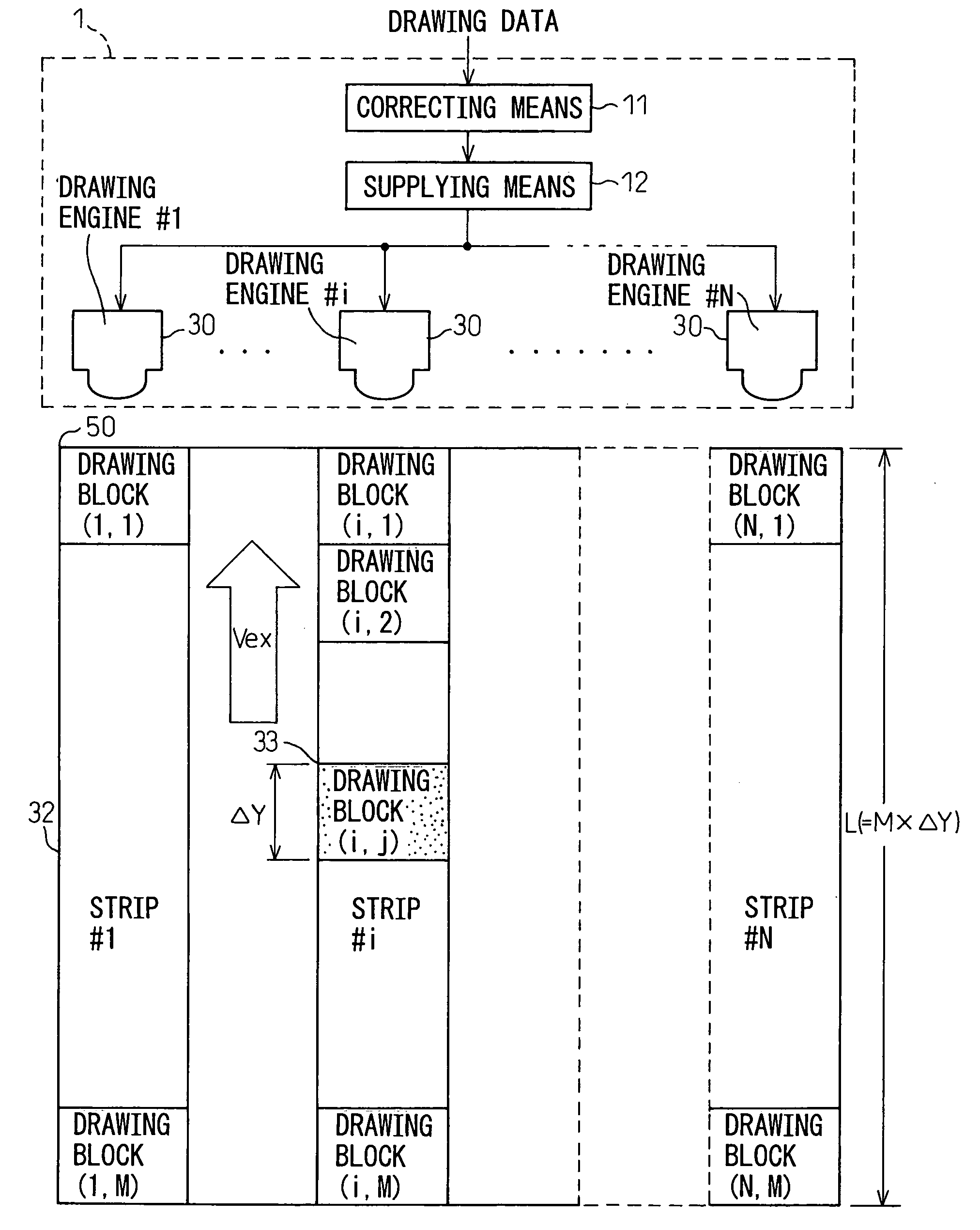
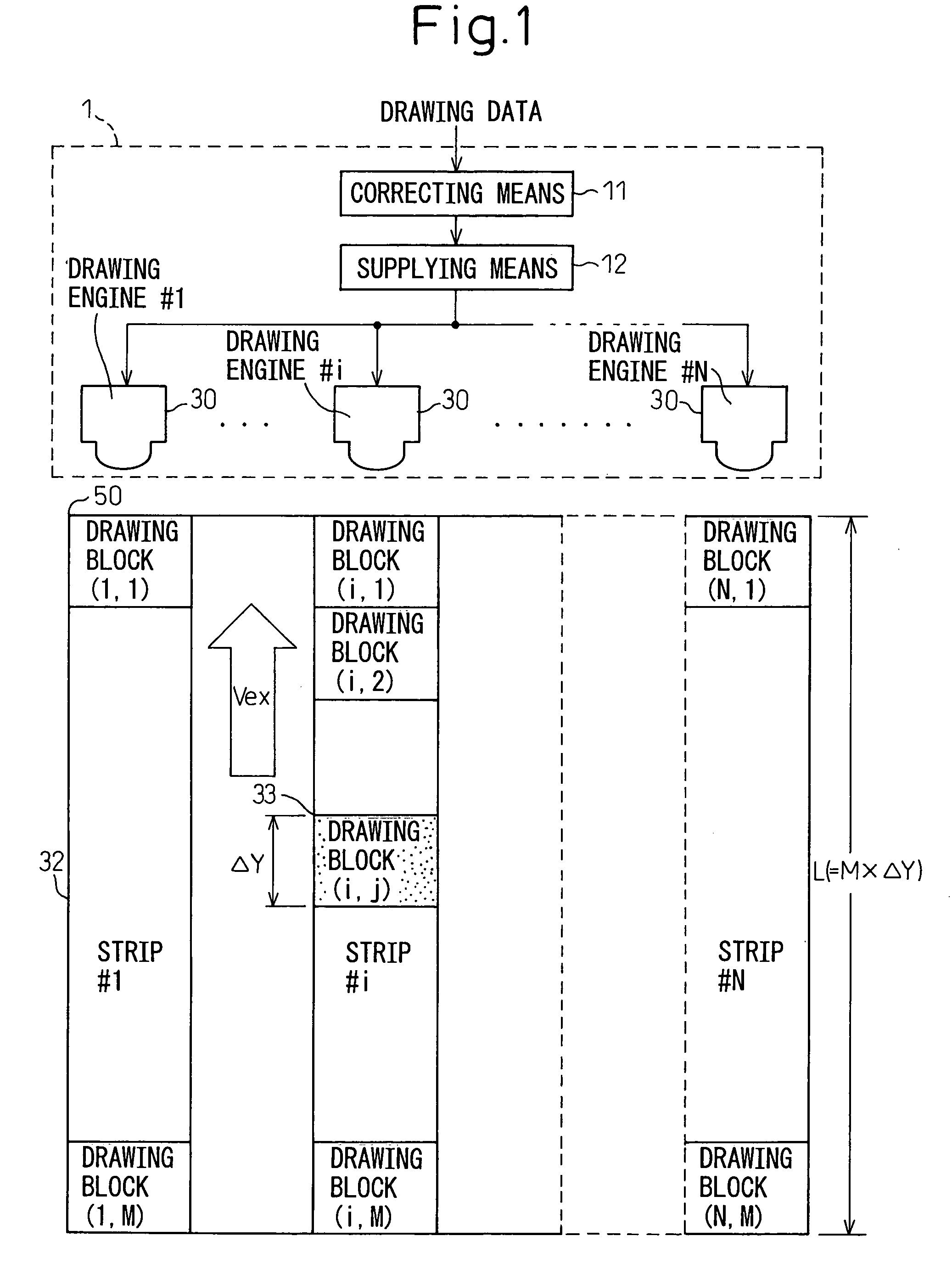
[0047] According to the drawing apparatus of the present invention, attention is paid to the fact that there occurs a difference between the design spacing and the actual spacing of the drawing devices in the drawing head, and the optimum corrected drawing data is generated by correcting the drawing data based on the above difference and the drawing pattern is formed based on the corrected drawing data by supplying the corrected drawing data to the drawing engine at the optimum timing based on the actual spacing of the drawing devices; as a result, stable drawing operations can be performed efficiently while maintaining the high resolution performance as intended.

Problems solved by technology

As bitmap data requires a huge amount of data for storage, generating and storing the bitmap data prior to drawing would not be preferable as it would consume a large amount of memory resources.
Accordingly, if the number, k, of light sources is sufficiently large, then even if some of the k light sources fail to emit light properly due, for example, to the failure of driving transistors in the LCD or of micromirrors in the DMD in the patterning method using the DMD, the possibility that such failure will have a serious effect on the final exposure result is small.
In reality, however, due to variations in hardware manufacturing, it is difficult to strictly satisfy these design requirements.
For example, in the case of the drawing data of bitmap form, as the data is generated by software on the externally connected computer, it is relatively easy to achieve the required data resolution b. On the other hand, the design condition requires that the light source spacing D in the exposure head be strictly equal to an integral multiple of (i.e., p times) the resolution (i.e., the unit pixel spacing) b of the bitmap data, but it is extremely difficult to strictly satisfy this design requirement in actual hardware because its mechanical construction is complicated.
For example, when the drawing apparatus is a direct exposure apparatus, it is difficult to achieve the light source spacing as designed by finely adjusting the optics of the light sources mounted in the drawing engine.
As a result, the intended resolution performance cannot be obtained.

Method used


Image

  • Drawing apparatus and drawing method
  • Drawing apparatus and drawing method
  • Drawing apparatus and drawing method

Examples


Embodiment Construction

[0072] While the present invention can be applied to any drawing apparatus whether it be a direct exposure apparatus (maskless exposure apparatus), an inkjet drawing apparatus, or a printing apparatus such as a laser printer, the following description deals with a direct exposure apparatus as one embodiment of the invention.

[0073] As previously described with reference to FIG. 1, the exposure apparatus according to the present invention comprises: correcting means for generating corrected drawing data by correcting the drawing data (bitmap data of resolution b) based on the difference between the design spacing D(=pb, where p is an integer) and the actual spacing E of the light sources constituting the exposure head; and supplying means for supplying the drawing engine with just the corrected drawing data necessary for direct drawing to a drawing block that the drawing engine can draw at a time on the drawing target surface, each time the drawing target substrate moves in relative ...


PUM

PropertyMeasurementUnit
displacementaaaaaaaaaa
wavelengthaaaaaaaaaa

Abstract

A drawing apparatus, for forming a desired drawing pattern by drawing the pattern directly on a drawing target surface using a drawing engine equipped with a plurality of drawing devices arranged along a direction of relative movement of the drawing target surface, the drawing engine being designed so that the design spacing of the thus arranged drawing devices is equal to a product of a unit pixel spacing in drawing data and an integer, comprises: correcting means for generating corrected drawing data by correcting the drawing data based on the difference between the design spacing and the actual spacing of the drawing devices; and supplying means for supplying the drawing engine with the corrected drawing data just necessary for direct drawing to a drawing block that the drawing engine can draw at a time on the drawing target surface, each time the drawing target substrate moves in relative fashion by a distance corresponding to an actual pixel spacing that is obtained by dividing the actual spacing of the drawing devices by that integer.

Description

BACKGROUND OF THE INVENTION [0001] 1. Field of the Invention [0002] The present invention relates to a drawing apparatus, and to a drawing method, for forming a desired drawing pattern by directly drawing the pattern on a drawing target surface using a drawing engine equipped with a plurality of drawing devices arranged in the direction of the relative movement of the drawing target surface, wherein the drawing engine is designed so that the design spacing of the thus arranged drawing devices is equal to an integral multiple of a unit pixel spacing in the drawing data. [0003] 2. Description of the Related Art [0004] Generally, a wiring pattern on a wiring substrate is formed by exposing the substrate, based on wiring pattern design data, and by developing and printing the desired pattern on the substrate, followed by etching. In the exposure process, a photomask is usually used. [0005] On the other hand, a patterning method based on direct drawing that does not use any photomasks ha...

Claims


Application Information

Patent Timeline
Patent Type & Authority Applications(United States)
IPC IPC(8): G06T11/20B41J2/01G03F7/20H01L21/027H05K3/00
CPCG03F7/70291G06T7/0006G03F7/70508G03F7/20
Inventor SEKIGAWA, KAZUNARI
Owner SHINKO ELECTRIC IND CO LTD
Why Eureka
Eureka Blog
Learn More