Sheet finisher and control method thereof

a technology of sheet finisher and control method, which is applied in the direction of electrographic process, instruments, transportation and packaging, etc., can solve the problems of reducing the processing capability of sheet finisher, increasing costs, and reducing the efficiency of sheet finisher, so as to reduce the frequency of switching the sheet conveyance path, reduce the reduction of the processing performance of the system, and avoid stacking

Inactive Publication Date: 2006-02-02
KONICA MINOLTA BUSINESS TECH INC
View PDF7 Cites 9 Cited by
  • Summary
  • Abstract
  • Description
  • Claims
  • Application Information

AI Technical Summary

Benefits of technology

[0011] The present invention is intended to avoid reduction of the processing capacity of a sheet finisher as described above. The object of the present invention is to provide a sheet finisher wherein a sheet bundle not having been subjected to the process of binding is stacked on a sheet bundle having been subjected to the process of binding, and these sheet bundles are integrated into one bundle, which is ejected to the ejection tray, thereby minimizing the frequency of switching a sheet conveyance path.
[0019] The Item (1) reduces the frequency of switching the sheet conveyance path of the sheet finisher and minimizes reduction in the processing performances of a system composed of the image forming apparatus and sheet finisher. Further, the sheet bundle having been subjected to the process of binding and the sheet bundle not having been subjected to the process of binding constitutes one part. This part constituted in this manner is handled as one body and is ejected to the ejection tray. Such functions of the sheet finisher are provided by the Item (1).
[0021] The Item (3) avoids stacking of sheet bundles in excess of the maximum stacking capability of the sheet stacking means. This arrangement avoids incorrect binding or ejection of the sheet bundles.

Problems solved by technology

Two sheet conveyance paths arranged in such an apparatus causes increased costs and discourages downsizing of the apparatus.
The switching operation frequently repeated drastically reduces the processing capability of the sheet finisher, with the result that the image forming apparatus is placed in the operation wait status more frequently.

Method used


Image

  • Sheet finisher and control method thereof
  • Sheet finisher and control method thereof
  • Sheet finisher and control method thereof

Examples


Embodiment Construction

[0030] The following describes the embodiments of the present invention with reference to drawings.

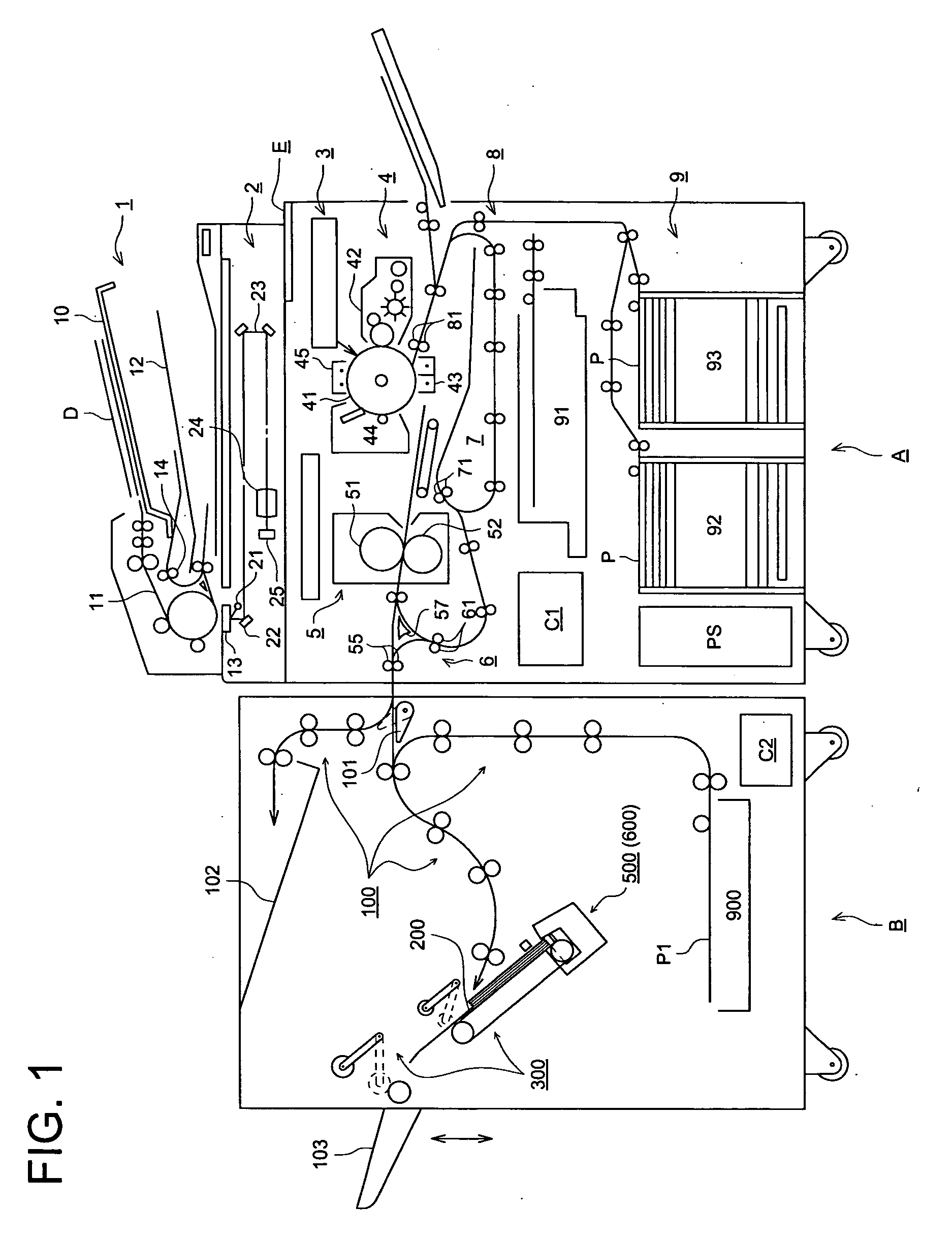
[0031]FIG. 1 is a conceptual diagram representing an image forming system wherein the sheet finisher and image recording apparatus are connected with each other.

[0032] The image forming apparatus A is a digital copying machine for forming an image using a known electrophotographic technology. An automatic document feeder 1 is installed on the top of the image forming apparatus A, which is connected with a sheet finisher B.

[0033] The image forming apparatus A comprises an automatic document feeder 1, a reading means 2, a writing means 3, an image forming means 4, a fixing means 5, a reversing or ejecting means 6, a re-feeding means 7, a sheet conveyance means 8, a sheet feeding means 9, a control means C1 and an operation and display means E.

[0034] The automatic document feeder 1 ensures that the documents D placed on the document platen 10 are fed one by one to a document conveyanc...


PUM


Abstract

A sheet finisher includes: a sheet stacker for stacking sheets outputted from an image forming apparatus to form a sheet bundle; a binder for binding the sheet bundle stacked on the sheet stacker; an ejection device for ejecting out of the sheet finisher at least one of the sheet bundle stacked on the sheet stacker and the sheet bundle which has been bound; an ejection tray for stacking the ejected sheet bundle or the bound sheet bundle sequentially; and a controller for controlling the ejection device to make the bound sheet bundle to wait on the sheet stacker, to make a sheet outputted from the apparatus which have not been bound to stack sequentially on the bound sheet bundle, and to make the bound sheet bundle and the sheet stacked on the bound sheet bundle as a unit to eject to the ejection tray.

Description

[0001] This application claims priority from Japanese Patent Application No. 2004-225297 filed on Aug. 2, 2004, which is incorporated hereinto by reference. BACKGROUND OF THE INVENTION [0002] The present invention relates to a sheet finisher and control method thereof, wherein the sheet finisher that receives a sheet with an image formed thereon by an image forming apparatus such as a copier and printer, applies a process of binding to the sheet by means of a binding device, and ejects the sheet to an ejection tray. [0003] In a sheet finisher, the sheets with images formed thereon by an image forming apparatus are stacked by a predetermined stacking means and are formed into a bundle of sheets, which are then provided with a process of binding to create a booklet or a document. This sheet finisher is widely used as a peripheral apparatus connected with an image forming apparatus. [0004] Further, the disclosed sheet finishers include the apparatus provided with a punching means for p...

Claims


Application Information

Patent Timeline
IPC IPC(8): B65H39/02
CPCB42C1/12B65H31/00B65H31/06B65H31/3027B65H2801/27B65H2301/163B65H2301/42262B65H2301/42266B65H31/3081
Inventor TANIGAMI, SHINYAUSHIO, MASARUHOSOI, KENICHI
Owner KONICA MINOLTA BUSINESS TECH INC
Why Eureka
Try Eureka