
Adaptive scissors

a technology of scissors and handles, applied in the direction of metal working devices, etc., can solve the problems of difficult angles and curves, inability to achieve the desired effect, and subtle adjustments of cutting detail work,

Inactive Publication Date: 2006-02-02
CAREY NANCY DAVIDSON
View PDF99 Cites 13 Cited by
  • Summary
  • Abstract
  • Description
  • Claims
  • Application Information

AI Technical Summary

Benefits of technology

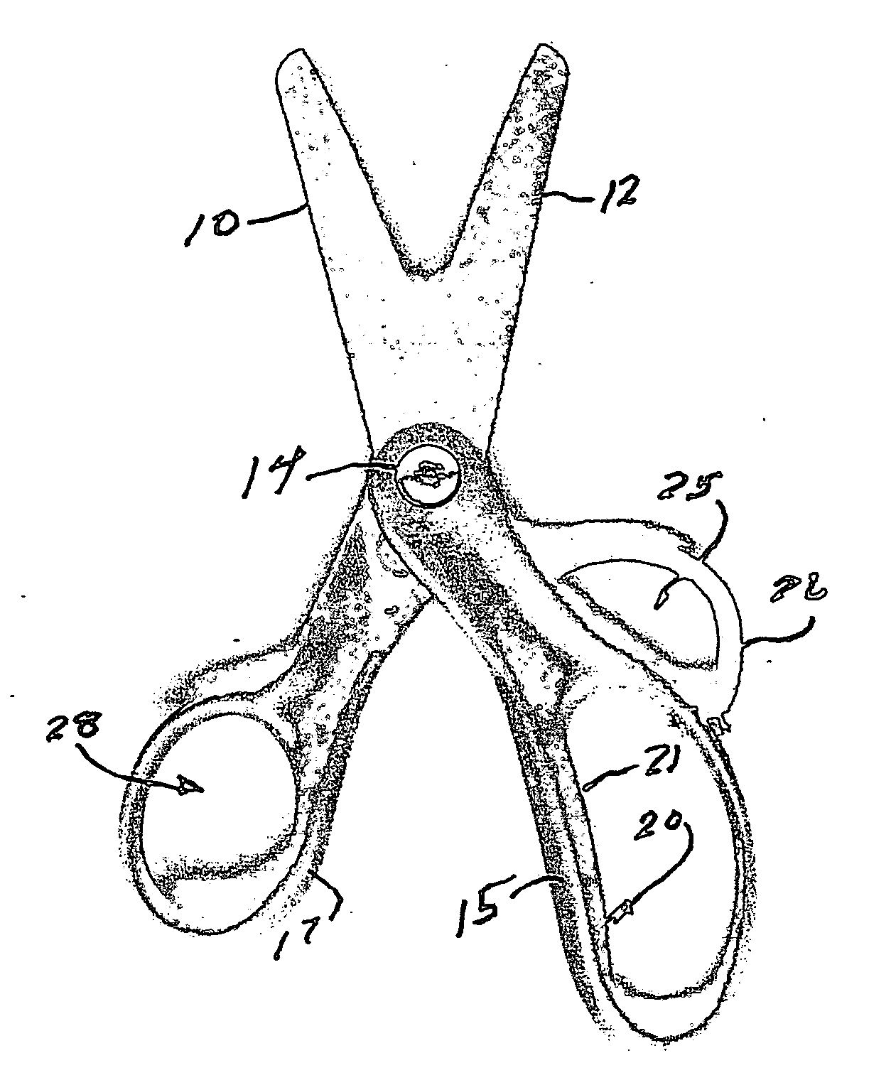
[0006] In accordance with this invention, an underside or lower scissors handle, which is conventionally attached to the upper blade of a pair of scissors, is provided with a separate, appropriately sized, additional hole or loop-like band for receiving the index finger of the user. This additional index finger hole is located forward of the main lower finger opening. This unique placement of a separate index finger hole, which is a primary feature of this invention, isolates the index finger against the shaft of the scissors and closer to the pivot point of the blades, and allows the index finger to guide advancing motion of the scissor blades to the right or left as needed to follow a desired path or pattern, for example forming or following a curve.
[0007] A separate third hole for placement of the index finger makes these scissors unique. Isolating the index finger against the shaft of the scissor handle provides stability and strength and allows the index finger to adjust or “guide” the scissors to the left or right making easy and subtle adjustments as needed to negotiate curves and angles as in following a pattern. Otherwise, with standard scissors many children place the index finger in the large loop along with one or more of the middle fingers and do not achieve the desired action. In so doing, they tend to extend the index finger out rather than maintaining it on the shaft of the scissor handle. This incorrect placement creates a situation where movements of the wrist adjust the scissors. These movements are bigger, making subtle adjustments for cutting detail work, angles, and curves more difficult, and typically not very accurate in reference to the cutting line.
[0008] Another feature of the invention relates to the “thumb hole” in the upper handle, which normally receives the thumb of the user's hand. In accordance with this other feature of the invention, the inner diameter of such upper handle thumb hole is limited with a suitable restraint, such that the thumb enters only by an amount sufficient to keep the thumb in flexion, and not far enough to place the thumb in extension. This maintains flexibility of the “web space” between the thumb and the side of the hand, and allows for greater leverage when opening and closing the scissors; if the thumb is held in extension, leverage is substantially reduced. The requisite reduction in thumb hole diameter can be readily achieved by partially filing the thumb hole with a predetermined amount of padding, i.e. a covered ring of foam or an equivalent device, added to the thumb hole. The exact amount of restriction will depend upon the size of a user's outer thumb joint, but it should be sufficient to impede thumb thrust into and through the thumb hole.

Problems solved by technology

Otherwise, with standard scissors many children place the index finger in the large loop along with one or more of the middle fingers and do not achieve the desired action.
In so doing, they tend to extend the index finger out rather than maintaining it on the shaft of the scissor handle.
This incorrect placement creates a situation where movements of the wrist adjust the scissors.
These movements are bigger, making subtle adjustments for cutting detail work, angles, and curves more difficult, and typically not very accurate in reference to the cutting line.

Method used


Image

  • Adaptive scissors
  • Adaptive scissors
  • Adaptive scissors

Examples


Embodiment Construction

[0017] Referring to FIGS. 1 and 2, a scissors tool according to the present invention includes an upper blade 10 and lower blade 12, connected by a hinge pin 14 providing a pivot means for opening a closing action of the blades. The forward end of the blades forms the forward tip of the scissors. A handle at the rear end of the scissors comprises a lower handle part 15 attached to blade 10 and an upper handle part 17 attached to blade 12, both extending rearward from hinge pin 14. Lower handle part 15 is provided with an elongated aperture 20 of generally oval shape, and (as in most instances) including a flattened interior surface 21 in the region where the grips or handle parts 15,17 come together when the blades are closed.

[0018] On the forward end of lower handle part 15 there is a smaller secondary aperture 25 defined by a generally U-shaped ring or band 26 that is attached at its ends into the exterior forward sides of lower handle 15. This aperture 25 assures a separate loca...


PUM


Abstract

In accordance with this invention, an underside or lower scissors handle, which is conventionally attached to the upper blade of a pair of scissors, is provided with a separate, appropriately sized, additional hole or loop-like band for receiving the index finger of the user. This additional index finger hole is located forward of the main lower finger opening. This unique placement of a separate index finger hole, which is a primary feature of this invention, isolates the index finger against the shaft of the scissors and closer to the pivot point of the blades, and allows the index finger to guide advancing motion of the scissor blades to the right or left as needed to follow a desired path or pattern, for example forming or following a curve. A separate third hole for placement of the index finger makes these scissors unique. Isolating the index finger against the shaft of the scissor handle provides stability and strength and allows the index finger to adjust or “guide” the scissors to the left or right making easy and very subtle adjustments as needed to negotiate curves and angles as in following a pattern. Another feature relates to the “thumb hole” in the upper handle. The inner diameter of such upper handle thumb hole is limited with a suitable restraint, such that the thumb enters only by an amount sufficient to keep the thumb in flexion, and not far enough to place the thumb in extension.

Description

PRIOR APPLICATION [0001] This application claims the priority of and is based upon, and hereby incorporates by reference the entire disclosure of, U.S. Provisional Application for ADAPTIVE SCISSORS, U.S. Ser. No. 60 / 591,853 filed 28 Jul. 2004.BACKGROUND OF THE INVENTION [0002] This invention relates to the creation and placement of finger and thumb holes in the handles of scissors. For purposes of this invention, the lower handle is part of the upper blade and the holes in the lower handle are deemed the finger hole or holes, the upper handle is part of the lower blade, and a thumb hole is formed in the upper handle. These handles are attached by a suitable pivot, whereby manipulation of the handles toward and away from each other causes corresponding opening and closing action of the blades. BACKGROUND OF THE INVENTION [0003] With standard scissors many users, including younger children who are learning (or being taught) to cut with scissors, place their index finger in the elongat...

Claims


Application Information

Patent Timeline
IPC IPC(8): B26B13/00
CPCB26B13/20
Inventor CAREY, NANCY DAVIDSON
Owner CAREY NANCY DAVIDSON
Learn More