Coated substrates
a coating substrate and photocatalytic technology, applied in the direction of physical/chemical process catalysts, metal/metal-oxide/metal-hydroxide catalysts, natural mineral layered products, etc., can solve the problems of low visible light transmission and high visible light reflection, and achieve excellent photocatalytic activity, reduce contact angle, and be deposited in a relatively short time
- Summary
- Abstract
- Description
- Claims
- Application Information
AI Technical Summary
Benefits of technology
Problems solved by technology
Method used
Image
Examples
examples 1-15
[0059] A ribbon of 1 mm thick soda lime float glass advancing at a lehr speed of 300 m / hour was coated with a two-layer coating as the ribbon advanced over the float bath at a position where the glass temperature was in the range of about 650° C. to about 670° C. The float bath atmosphere comprised a flowing gaseous mixture of nitrogen and 9% hydrogen at a bath pressure of approximately 0.15 mbar.
[0060] Layer 1 (the first layer to be deposited on the glass) was a layer of silicon oxide. Layer 1 was deposited by causing a gaseous mixture of monosilane (SiH4, 60 ml / min), oxygen (120 ml / min), ethylene (360 ml / min) and nitrogen (8 litres / min) to contact and flow parallel to the glass surface in the direction of movement of the glass using coating apparatus as described in GB patent specification 1 507 966 (referring in particular to FIG. 2 and the corresponding description on page 3 line 73 to page 4 line 75) with a path of travel of the gaseous mixture over the glass surface of approx...
examples 16-19
[0064] Examples 16-19 were conducted under the same conditions as Examples 1-15 except that the bath pressure was approximately 0.11 mbar, extraction for deposition of the silica undercoat (layer 1) was approximately 0.7 mbar, the titanium tetrachloride bubbler was maintained at a temperature of approximately 100° C., the ethyl acetate bubbler was maintained at a temperature of approximately 45° C. and the delivery lines were maintained at a temperature of approximately 220° C.
[0065] The flow rates of nitrogen carrier gas, and the estimated flow rates of entrained titanium tetrachloride and entrained ethyl acetate are disclosed for each of the examples 16-19 in Table 1.
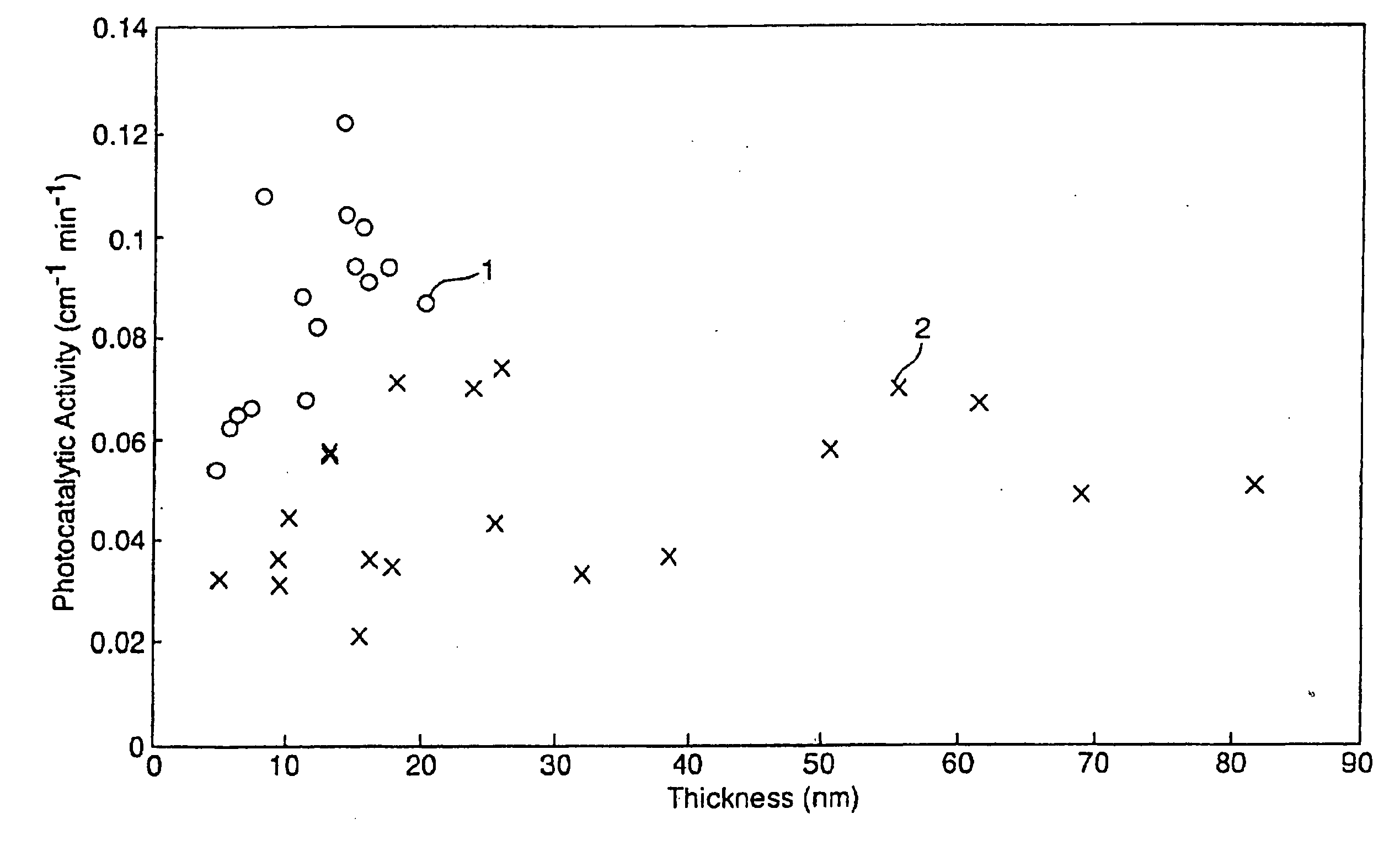
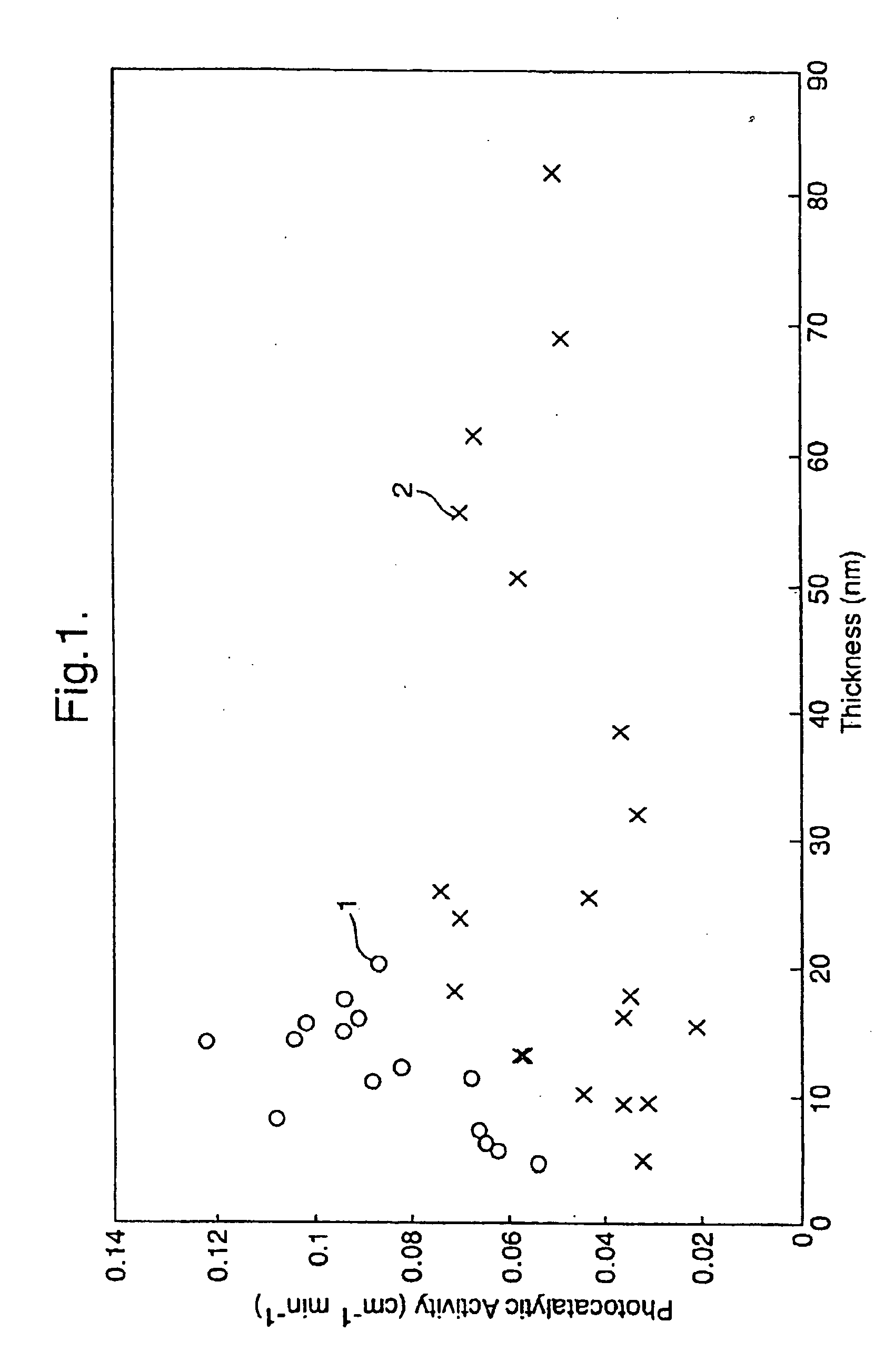
[0066] Values of the estimated thickness of layer 2 (the titanium oxide layer), and values of visible reflection measured on the coated side, L* and haze of the coated glasses are described in Table 2 for each of the Examples 16-19.
[0067] The initial peak height and initial peak area of the IR peaks corresponding t...
examples 20-27
[0071] The Examples 20-27 were conducted under the same conditions as Examples 1-15 except that layer 2 was deposited from a gaseous mixture comprising titanium tetraethoxide entrained in nitrogen carrier gas by passing the carrier gas through a bubbler containing titanium tetraethoxide maintained at a temperature of 170° C. The flow rates of nitrogen carrier gas (measured at 20 psi) and titanium tetraethoxide are described in Table 4 for each of the Examples 20-27. The flow rate of bulk nitrogen gas was 8.5 l / min (measured at 20 psi).
[0072] The properties of the two-layer coatings were measured. Values of the thickness of layer 2 (the titanium oxide layer), and values of the visible reflection measured on the coated side and haze of the coated glasses are described in Table 5 for the Examples 20-27. The haze of each coated glass was below 0.7%.
[0073] The photocatalytic activity and static water contact angle of the coated glasses were determined. The initial peak height and initi...
PUM
| Property | Measurement | Unit |
|---|---|---|
| thickness | aaaaa | aaaaa |
| water contact angle | aaaaa | aaaaa |
| haze | aaaaa | aaaaa |
Abstract
Description
Claims
Application Information
 - R&D
- Intellectual Property
- Life Sciences
- Materials
- Tech Scout
- Unparalleled Data Quality
- Higher Quality Content
- 60% Fewer Hallucinations
Browse by: Latest US Patents, China's latest patents, Technical Efficacy Thesaurus, Application Domain, Technology Topic, Popular Technical Reports.
© 2025 PatSnap. All rights reserved.Legal|Privacy policy|Modern Slavery Act Transparency Statement|Sitemap|About US| Contact US: help@patsnap.com


