
Terminal connection device, connection control device, and multi-function telephone terminal

Inactive Publication Date: 2006-01-19
SOFTBANK GRP CORP
View PDF9 Cites 91 Cited by
  • Summary
  • Abstract
  • Description
  • Claims
  • Application Information

AI Technical Summary

Benefits of technology

[0008] By this configuration, it is determined, on the basis of the destination telephone number contained in the connection request, which of the packet network and the public switched telephone network the terminal connection device sends the connection request to, and therefore it is avoided that the user of the communication terminal has to determine which of the packet network and the public switched telephone network is used for communication.
[0011] By this configuration, when the destination telephone number is concatenated with predetermined identification information such as a succession of a particular number which is distinct from the telephone number itself, the connection request is always sent to the public switched telephone network, and therefore the user of the telephone terminal can arbitrarily and easily designates the public switched telephone network for communication.
[0015] In accordance with the third to fifth features of the present invention, the connection processing unit transmits to the telephone terminal, which is sending a connection request, the audible signal indicating which of the communication path routed only through the packet network and the communication path routed through both the packet network and the public switched telephone network is provided for the communication with the telephone terminal to which the destination telephone number is assigned. Accordingly, the user can easily know which of the communication path routed only through the packet network and the communication path routed through both the packet network and the public switched telephone network is provided for the communication with the telephone terminal to which the destination telephone number is assigned.
[0017] By this configuration, the connection processing unit selects which of the public switched telephone network and the packet network is used for voice conversation while the packet transmitter receiver unit transmits and receives the packet data converted from the voice band signals with the IP network through the asymmetric digital subscriber line (ADSL). Because of this, an IP phone service enabling broadband communications can be used only by connecting an conventional telephone line (subscriber line) so that it is possible to dispense with cumbersome connecting and wiring work, and therefore it is avoided that the user of the communication terminal has to determine which of the packet network and the public switched telephone network is used for communication.
[0023] By this configuration, the packet transmitter receiver unit transmits and receives, with the packet network via the asymmetric digital subscriber line, the packet data which is communicated with the personal digital assistant through the communication card inserted into the slot, and therefore a continuous connection Internet service can be provided for the personal digital assistant without need for troublesome connecting and wiring work.

Problems solved by technology

However, there is a problem that the user of the above communication terminal must confirm whether or not the communication with the destination communication terminal is possible through the packet network and instruct the terminal connection device to use which of the packet network and the public switched telephone network for communication.

Method used


Image

  • Terminal connection device, connection control device, and multi-function telephone terminal
  • Terminal connection device, connection control device, and multi-function telephone terminal
  • Terminal connection device, connection control device, and multi-function telephone terminal

Examples


first embodiment

(Network Configuration Including Connection Devices and Connection Control Devices)

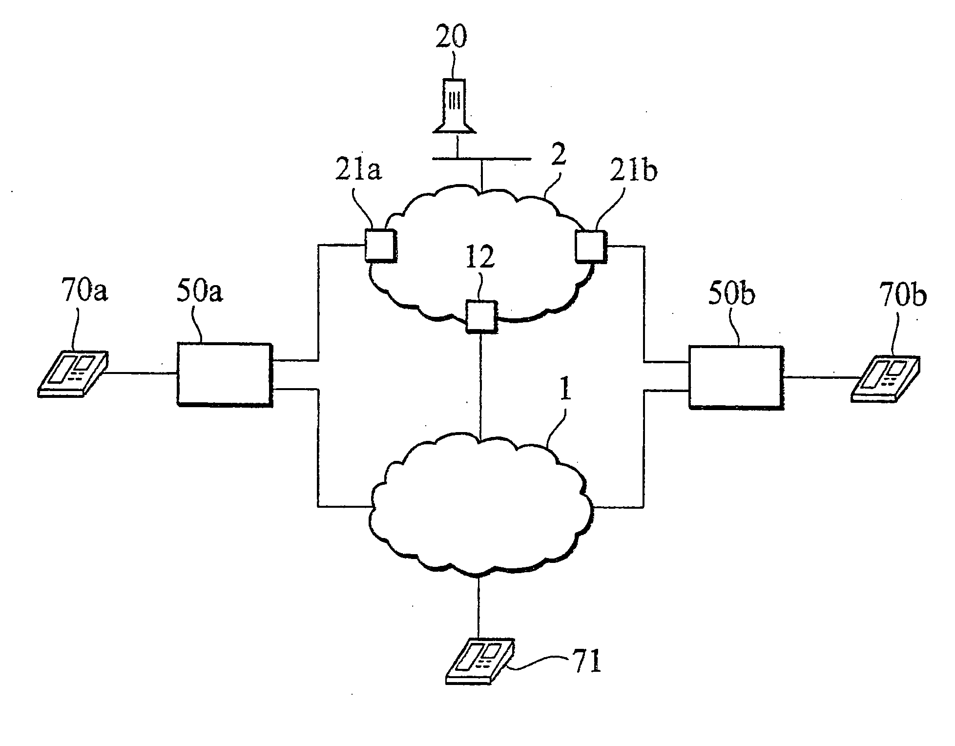
[0041] A terminal connection device and a connection control device in accordance with an embodiment of the present invention will be explained in conjunction with the accompanying drawings.

[0042]FIG. 1 is a schematic diagram showing the network including the terminal connection device and the connection control device in accordance with the present embodiment. As shown in FIG. 1, a VOIP gateway 50a (the terminal connection device) is connected to a public switched telephone network 1 (referred to herein as PSTN 1) which is a network for providing a plain old telephone system (POTS) and an IP network 2 which is a network for providing an IP telephone service. In addition, a telephone terminal 70a (communication terminal) which is an analog telephone terminal for transmitting and receiving voice band signals is connected to the VOIP gateway 50a.

[0043] The VOIP gateway 50a transmits and receives voi...


PUM


Abstract

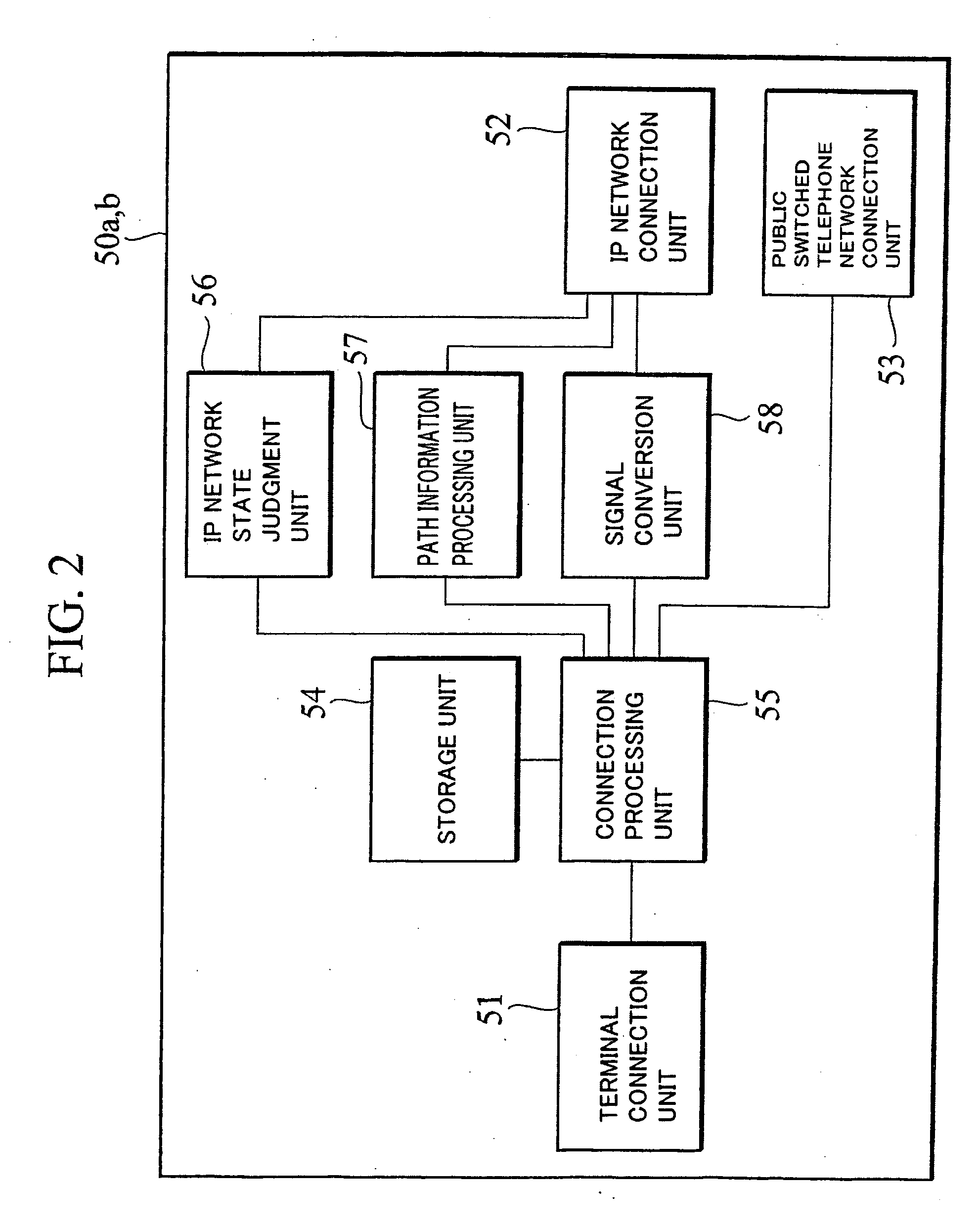
The VoIP gateway 50a in accordance with the present invention serves to send a connection request to either the IP network 2 or the PSTN 1 on the basis of the information stored in the VOIP gateway 50a and the destination telephone number contained in the connection request as sent from the telephone terminal 70a. Also, even if a connection request is decided to be sent to the IP network 2, the VOIP gateway 50a sends the connection request to the PSTN 1 when the IP network state judgment unit 56 judges that the communication through the IP network 2 is impossible. Furthermore, if a destination telephone number includes predetermined identification information, the VOIP gateway 50a can forcibly send the connection request to the PSTN 1.

Description

TECHNICAL FIELD [0001] The present invention relates to a terminal connection device, a connection control device and a multifunctional telephone terminal for providing telephone services on a packet network. BACKGROUND OF THE INVENTION [0002] Along with the recent advent of information technology (IT), IP telephone services have been provided on the basis of Voice over IP (VOIP) in addition to the conventional public telephone service (Plain Old Telephone System, POTS). [0003] In such circumstances, by connecting a communication terminal as conventionally used such as an analog telephone terminal to a terminal connection device, i.e., a VoIP gateway through which a packet network (IP network) provided for IP telephone service is connected to a public switched telephone network (PSTN) for providing a plain old telephone system, this communication terminal is available for communication with another communication terminal through either or combination of the packet network and the pu...

Claims


Application Information

Patent Timeline
Patent Type & Authority Applications(United States)
IPC IPC(8): H04L12/66H04L29/06H04M1/253H04M1/725H04M1/72502H04M3/08H04M3/12H04M3/22H04M7/00H04W76/02H04W88/14H04W88/16H04W92/02
CPCH04L29/06027H04L65/103H04M1/725H04M1/72502H04M3/08H04M3/12H04M3/2218H04M7/0057H04M7/006H04M7/0069H04W76/027H04W88/14H04W88/16H04W92/02H04L65/1043H04L65/104H04L65/1069H04L65/80H04M1/2535H04W76/18H04W40/14H04W92/06H04W88/06H04L12/66H04L65/1101
Inventor SON, MASAYOSHIKUROBE, MITSUO
Owner SOFTBANK GRP CORP
Learn More