Display device
a display device and display panel technology, applied in the direction of casings/cabinets/drawer details, identification means, instruments, etc., can solve the problems of causing a a large amount of unwanted electromagnetic wave radiation in the operation, etc., to prevent the deformation of the display panel, reduce the mass, and prevent the front panel from deforming
- Summary
- Abstract
- Description
- Claims
- Application Information
AI Technical Summary
Benefits of technology
Problems solved by technology
Method used
Image

Examples
first embodiment
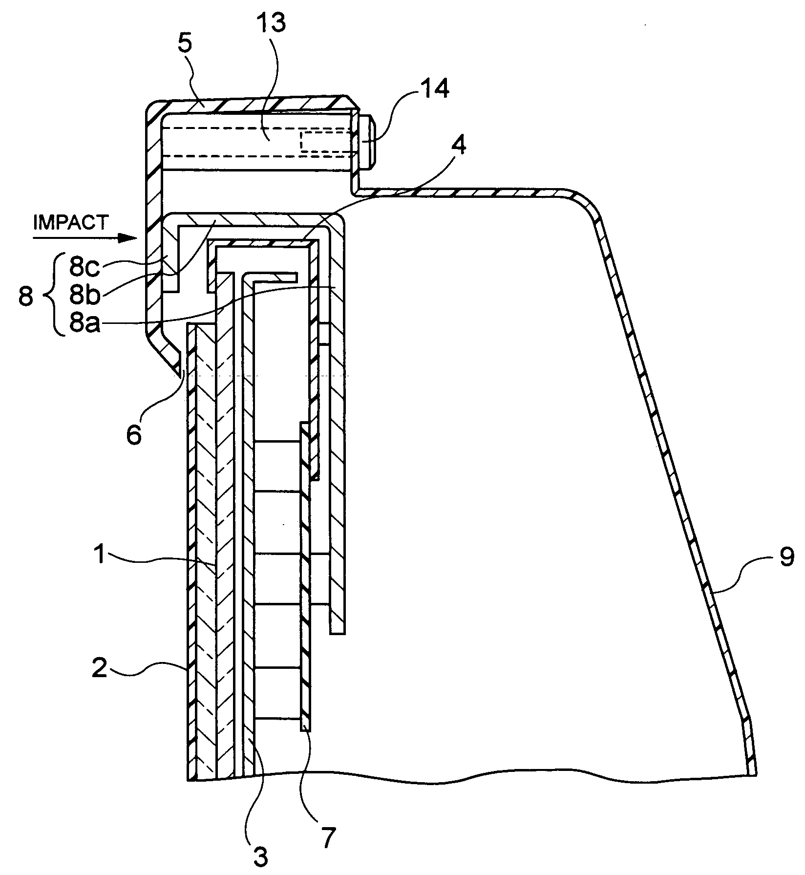
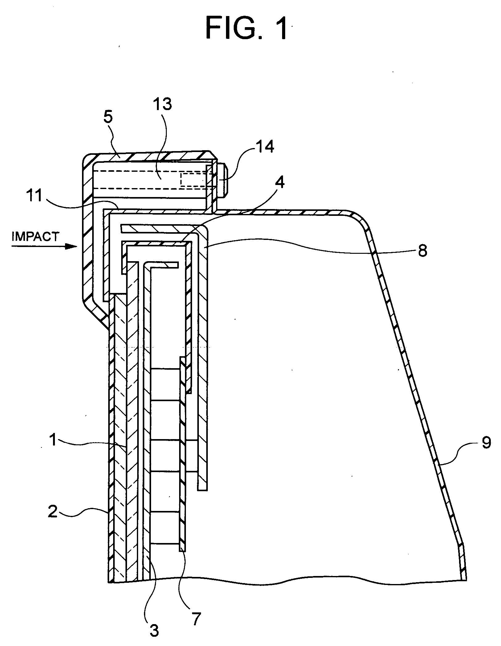
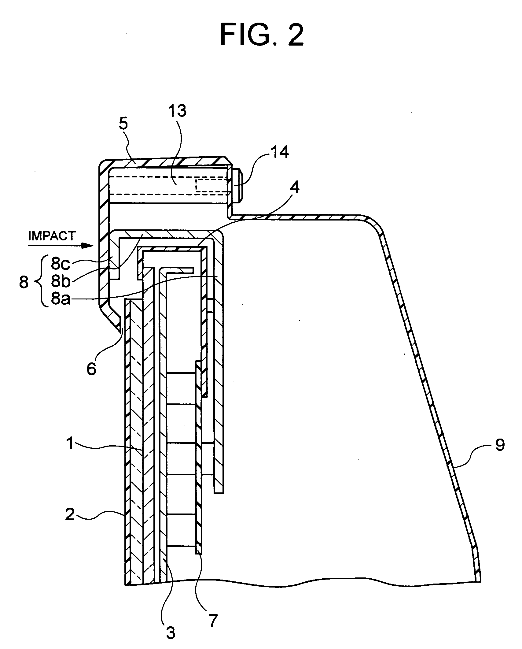
[0036] With reference to the attached drawings, explanation will be now made on embodiments of the present invention. First explained is the invention. FIG. 2 is a sectional view showing a structure of a plasma display device according to the present embodiment. The plasma display device in this embodiment is provided with a front panel 5 formed of resin in a frame form. Meanwhile, the front panel 5 is joined with a spacer 13 while the spacer 13 is joined with a back cover 9 by means of a bolt 14. Namely, the spacer 13 is circular in form forming a screw hole along the axis thereof. A bolt 14 is screwed in the screw hole. Note that the spacer 13 may be formed integral with the front panel 5 at the inward of the front panel 5. The front panel 5 and a back cover 9 form an exterior housing for the plasma display device.
[0037] A PDP 1 is provided at an interior of the exterior housing. A support (not shown) which is to support the PDP 1 is provided below the PDP 1. In the PDP 1, two non...
second embodiment
[0050] In this modification, by connecting the functional film 2 with the module plate 3 through the gasket 10, the functional film 2 can be grounded without providing a film ground metal. This can reduce the cost for the plasma display device because of no need of a film ground metal. The other operation and effect of the modification than the above is similar to the
[0051] Now explained is a third embodiment of the invention. FIG. 6 is a sectional view showing a plasma display device according to this embodiment. This embodiment is a combination of the first embodiment and the second embodiment, as shown in FIG. 6. Namely, in the plasma display device of this embodiment, the heat sink 8 is made in a squared-U form similarly to the first embodiment wherein the portion 8c is in abutment against the backside of the front panel 5. Meanwhile, similarly to the second embodiment, the module plate 3 is provided with an extended portion 3b extending frontward. The extended portion 3b has a ...
third embodiment
[0054] In this modification, the functional film 2 can be grounded to the module plate 3 through the gasket 10. This eliminates the necessity of a film ground metal, thus reducing the cost for the plasma display device. The other operation and effect of the modification than the above is similar to the
PUM
 Abstract
Description
Claims
Application Information
 - R&D
- Intellectual Property
- Life Sciences
- Materials
- Tech Scout
- Unparalleled Data Quality
- Higher Quality Content
- 60% Fewer Hallucinations
Browse by: Latest US Patents, China's latest patents, Technical Efficacy Thesaurus, Application Domain, Technology Topic, Popular Technical Reports.
© 2025 PatSnap. All rights reserved.Legal|Privacy policy|Modern Slavery Act Transparency Statement|Sitemap|About US| Contact US: help@patsnap.com