
Method and system for emergency control of a voice/data communications device

a voice/data communication and emergency control technology, applied in the field of internet telephony, can solve problems such as new challenges for the industry, network information, billing address, and inability to reliably handle emergency service requests

Inactive Publication Date: 2006-01-12
AT&T DELAWARE INTPROP INC
View PDF24 Cites 91 Cited by
  • Summary
  • Abstract
  • Description
  • Claims
  • Application Information

AI Technical Summary

Benefits of technology

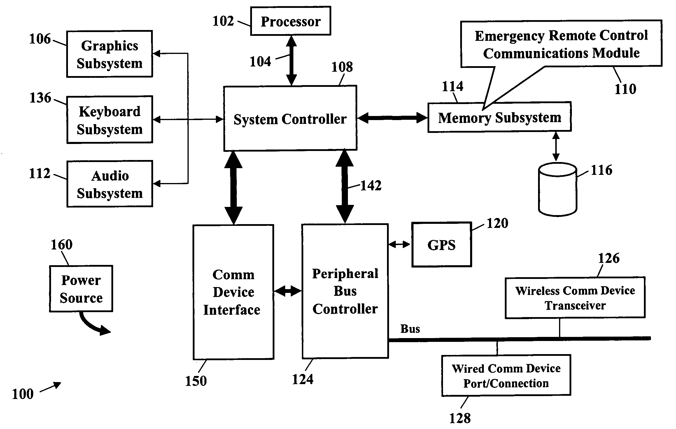
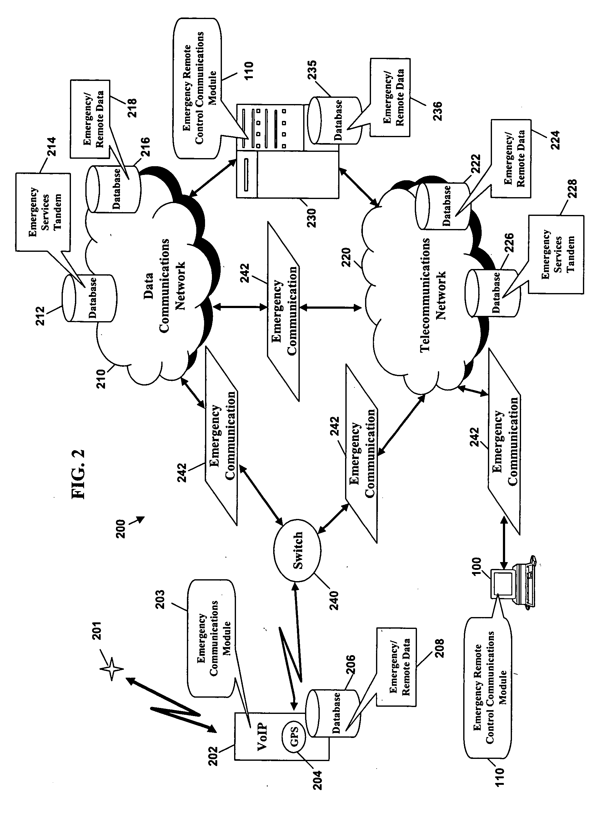
[0011] Typically, a calling party uses the VoIP communications device to communicate an emergency communications signal over a telecommunications network and/or a data network to an emergency communications address, or alternatively, to a public safety answering point (PSAP) associated with the emergency communications signal (e.g., a 911 call for help). The telecommunications network and/or the data network detects, decodes, and/or connects the emergency communications signal to the emergency communications address or to an associated PSAP (or other associated emergency response center) and establishes a communications link. A responder communications device of the emergency communications address detects and decodes the emergency communications signal to obtain a communications address of the VoIP communications device (and/or of the peripheral communications device), emergency information, an emergency data communications address, and/or remote activation information. Thereafter, an emergency remote control computer software product (also referred to herein as the “Emergency Remote Control Communications Module (ERCCM)”) of the responder communications device (i.e., the responder communications device and/or another voice and/or data communications device of an emergency service provider, or, alternatively a telecommunications and/or data network component) generates an emergency remote control communications signal for communication with the VoIP communications device (and/or peripheral hardware and equipment) via the telecommunications network and/or the data network. When a communications link between the VoIP communications device (and/or peripheral hardware equipment) and the responder communications device communicates the emergency remote control communications signal, the emergency remote control communications signal instructs and/or commands access to, monitoring of, activation of, deactivation, and/or other management of subsystems of the VoIP communications device (and/or the peripheral hardware and equipment). For example, the responder communications device may use the remote activation information that identifies and provide operating parameters for a location position system of the VoIP communications device. And, the Emergency Remote Control Communications Module may generate an emergency remote control communications signal to activate the location co-ordinate system of the VoIP communications device and receive up-to-date and/or real time positioning information of the VoIP communications device. In addition, the emergency remote control communications signal may instruct the telecommunications network and/or data network (and/or the VoIP communications device) to not activate and/or to deactivate an alert of an incoming communication from the responder communications device. For example, if the calling party of the VoIP communications device calls to report a violent crime, a kidnapping, and/or another sensitive emergency and the communications link is interrupted and/or terminated, then the responder communications device may communicate the emergency remote control communications signal with instructions to the telecommunications network, the data network, and/or the VoIP communications device (and/or peripheral hardware and equipment) to quietly connect the emergency remote control communications signal without activating an alert such as a ringer, vibrator, visual indicator (e.g., flashing light), and/or another sensory device of the VoIP communications device (and/or peripheral hardware and equipment).
[0012] According to embodiments of this invention, a method of processing a emergency remote control communications signal includes receiving an emergency communications signal from a voice/data communications device (e.g., a VoIP communications device) to an emergency responder communications device, using the emergency communications signal to generate a emergency remote control communications signal, and communicating the emergency remote control communications signal to the communications address of the emergency site communications device. The emergency communications signal may include a communications signal, a communications address for communicating with an emergency site communications device (e.g., the VoIP communications device and/or peripheral hardware and equipment), remote activation data associated with the emergency site communications device, emergency data, and/or an emergency data communications address for accessing the emergency data. And, the emergency remote control communications signal may include a response communications signal (e.g., voice signal, text messaging signal, video signal, and/or others), the communications address of the emergency site communications device, a responder's communications address, a control parameter for accessing the emergen

Problems solved by technology

Along with these improvements comes new challenges for the industry.
However, when the caller uses a VoIP phone to request the emergency service, problems exist with routing and with dispatching appropriate emergency service providers.
For example, if the caller uses a wireless VoIP communications device, then the wireless VoIP communications device may be used at different geographic locations to make the request for the emergency service, and consequently some network information, like the billing address, is not reliable for routing and / or other processing of the emergency service request to a nearby emergency service provider that is equipped to respond to the emergency request.

Method used


Image

  • Method and system for emergency control of a voice/data communications device
  • Method and system for emergency control of a voice/data communications device
  • Method and system for emergency control of a voice/data communications device

Examples


Embodiment Construction

[0027] This invention now will be described more fully hereinafter with reference to the accompanying drawings, in which exemplary embodiments are shown. This invention may, however, be embodied in many different forms and should not be construed as limited to the embodiments set forth herein. These embodiments are provided so that this disclosure will be thorough and complete and will fully convey the scope of the invention to those of ordinary skill in the art. Moreover, all statements herein reciting embodiments of the invention, as well as specific examples thereof, are intended to encompass both structural and functional equivalents thereof. Additionally, it is intended that such equivalents include both currently known equivalents as well as equivalents developed in the future (i.e., any elements developed that perform the same function, regardless of structure).

[0028] Thus, for example, it will be appreciated by those of ordinary skill in the art that the diagrams, flowchart...


PUM


Abstract

Emergency remote control communications systems and methods provide remote access to, activation of, deactivation of, monitoring of, communications with, and / or otherwise management of a Voice-Over Internet Protocol (VoIP) communications device (and / or another peripheral communications device) in response to an emergency communication originating from the VoIP communications device. An emergency remote control communications software product detects an emergency communications signal, and, in response, generates an emergency remote control communications signal for communication to the VoIP communications device via a communications network.

Description

CROSS REFERENCE TO RELATED APPLICATIONS [0001] This application relates to applicant's co-pending application entitled “E911 Systems and Methods for VoIP / VoN,” (Attorney Docket 04-BS006 / BS040021) filed on Apr. 30, 2004, and of which the “Brief Summary of the Invention” and “Detailed Description of the Invention” sections are incorporated herein by this reference. [0002] This application relates to applicant's co-pending application entitled “Method and System for Routing Emergency Data Communications,” (Attorney Docket 04-BS032 / BS040189) filed on May 27, 2004, and of which the “Brief Summary of the Invention” and “Detailed Description of the Invention” sections are incorporated herein by this reference. NOTICE OF COPYRIGHT PROTECTION [0003] A portion of the disclosure of this patent document and its figures contain material subject to copyright protection. The copyright owner has no objection to the facsimile reproduction by anyone of the patent document or the patent disclosure, bu...

Claims


Application Information

Patent Timeline
IPC IPC(8): H04M11/04
CPCH04L29/06027H04M7/006H04M11/04H04M2242/04H04L67/322H04W4/22H04W76/007H04L65/1069H04W4/02H04W76/50H04W4/90H04L67/61H04L65/1094H04L65/1101
Inventor LALIBERTE, DONALD R.
Owner AT&T DELAWARE INTPROP INC
Learn More