
Method and apparatus for preparing a collection surface for use in producing carbon nanostructures

a carbon nanostructure and collection surface technology, applied in the field of carbon nanostructure manufacturing, can solve the problems of less effective or undesirable metal catalysts for promoting carbon nanostructure formation

Inactive Publication Date: 2006-01-12
CLEAN TECH INT
View PDF64 Cites 23 Cited by
  • Summary
  • Abstract
  • Description
  • Claims
  • Application Information

AI Technical Summary

Benefits of technology

"The present invention provides a method for producing a collection surface where high quality carbon nanostructures can be formed or collected. The method involves producing deposition conditions in a collection area above a reactant liquid containing one or more catalyst metals, and directing a carrier gas to flow over the surface of the reactant liquid and collect carbon nanostructures on the metal catalyst-prepared collection surface. The invention also includes an apparatus for preparing the collection surface and collecting carbon nanostructures on it. The technical effects of the invention include producing high-quality carbon nanostructures on a collection surface and minimizing interference with the deposition process."

Problems solved by technology

For example, the presence of free non-catalyst atoms (extraneous atoms other than those making up the carrier gas) at the collection surface may cause the extraneous atoms to be incorporated with the metal catalyst atoms deposited on the collection surface and make the metal catalyst less effective or undesirable for promoting carbon nanostructure formation.

Method used


Image

  • Method and apparatus for preparing a collection surface for use in producing carbon nanostructures
  • Method and apparatus for preparing a collection surface for use in producing carbon nanostructures
  • Method and apparatus for preparing a collection surface for use in producing carbon nanostructures

Examples


Embodiment Construction

[0016] The claims at the end of this application set out novel features which the Applicant believes are characteristic of the invention. The various advantages and features of the invention together with preferred modes of use of the invention will best be understood by reference to the following description of illustrative embodiments read in conjunction with the drawings introduced above.

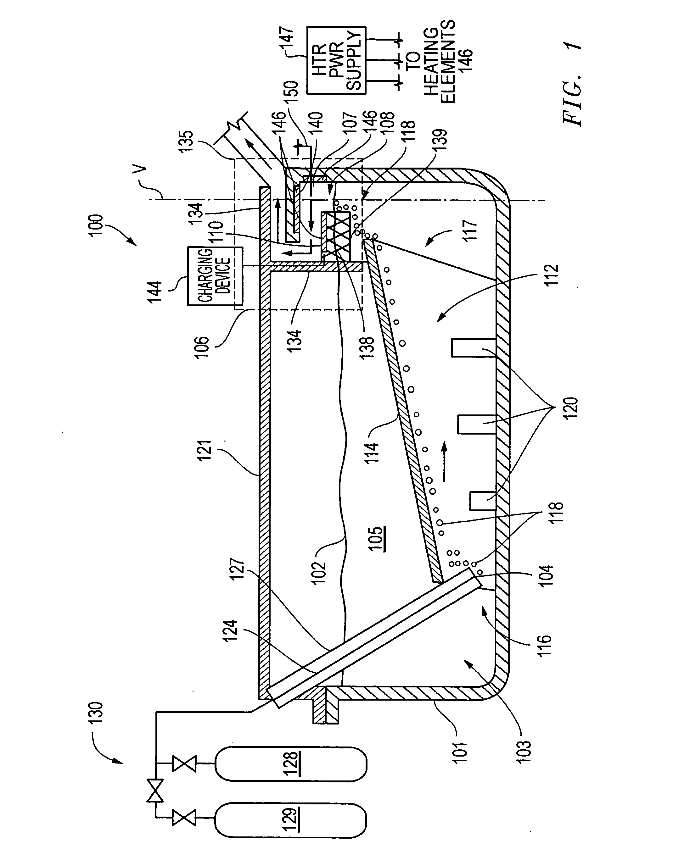
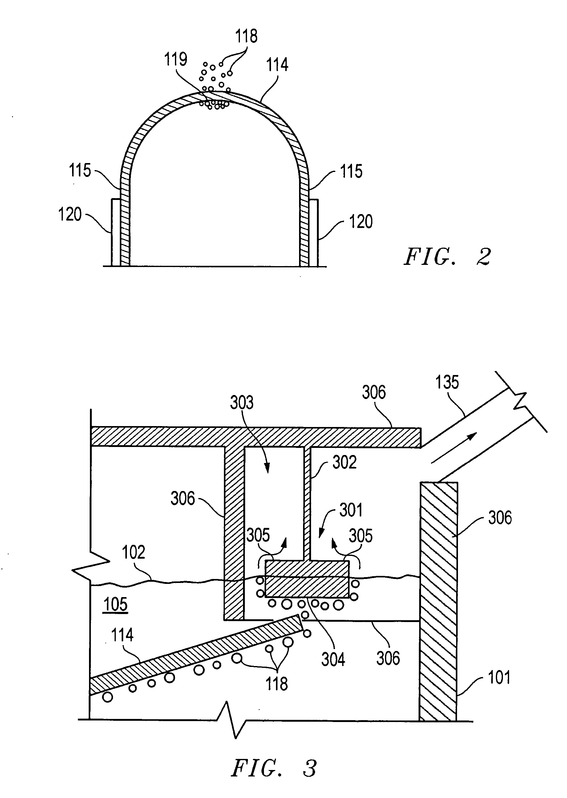
[0017] Referring to the diagrammatic representation of FIG. 1, an apparatus 100 for preparing a collection surface and producing carbon nanostructures according to the present invention includes a reactant liquid vessel 101 for containing a reactant liquid 105 at a reactant liquid level 102. An injection arrangement shown generally at reference numeral 103 allows a stream of feed material to be injected into reactant liquid vessel 101 at an injection point 104 below reactant liquid level 102. Apparatus 100 further includes a collection arrangement shown generally in dashed box 106. The illustrat...


PUM

PropertyMeasurementUnit
temperatureaaaaaaaaaa

Abstract

A method includes producing deposition conditions in a collection area above a reactant liquid containing one or more catalyst metals. The reactant liquid is maintained under conditions in which atoms of the catalyst metal may escape from the reactant liquid into the collection area. A suitable carrier gas is directed to traverse a surface of the reactant liquid and flow along a collection path that passes over a collection surface in the collection area. This flow of carrier gas is maintained so that escaped atoms of catalyst metal are entrained in the gas traversing the surface of the reactant liquid and are deposited on the prior to or concurrently with nanocarbon structure formation at the collection surface.

Description

CROSS-REFERENCE TO RELATED APPLICATION [0001] This application is a continuation-in-part of U.S. patent application Ser. No. 10 / 887,695, filed Jul. 9, 2004 and entitled “Method and Apparatus for Producing Carbon Nanostructures.” The Applicant claims the benefit of this prior application pursuant to 35 U.S.C. §120. The entire content of this prior application is incorporated herein by this reference.TECHNICAL FIELD OF THE INVENTION [0002] The present invention relates to the manufacture of carbon nanostructures. More particularly, the invention relates to a method and apparatus for producing a collection surface on which the chemical and physical conditions are controlled to facilitate the formation of carbon nanostructures. BACKGROUND OF THE INVENTION [0003] Carbon nanostructures have received a great deal of interest since their discovery. It has been suggested that carbon nanostructures may have important applications in electronics, in materials sciences, and in a number of addit...

Claims


Application Information

Patent Timeline
Patent Type & Authority Applications(United States)
IPC IPC(8): C01B31/02B01J8/18
CPCB01J4/002C01B31/30B01J19/24B01J19/26B01J21/185B01J23/10B01J23/24B01J23/38B01J23/70B01J37/023B01J2219/00119B01J2219/00135B01J2219/00182B82Y30/00B82Y40/00C01B31/0233B01J6/005Y10S977/842Y10S977/844C01B32/162C01B32/90
Inventor WAGNER, ANTHONY S.
Owner CLEAN TECH INT
Learn More