
Single crystal silicon micromachined capacitive microphone

a capacitive microphone and single crystal silicon technology, applied in the direction of piezoelectric/electrostrictive transducers, transducer types, electrostatic transducers of semiconductor, etc., can solve the problems of thermal mismatch tension, difficult to achieve such efforts, and low plate flatness

Inactive Publication Date: 2006-01-12
TU XIANG ZHENG
View PDF5 Cites 45 Cited by
  • Summary
  • Abstract
  • Description
  • Claims
  • Application Information

AI Technical Summary

Benefits of technology

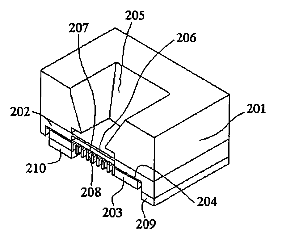
[0010] An important object of the present invention is therefore to improve upon the above-noted prior art technology, by providing a single crystal micromachined capacitive microphone whose capacitive elements are made up of two epitaxial single crystal silicon layers so as to cancel all thermal mismatched tension related problems forever.
[0011] A further object of the present invention is to provide a single crystal micromachined capacitive microphone having a flexible plate whose tension can be precisely defined by adjusting the doping concentration thereof.
[0013] Still another object of the present invention is to provide a single crystal micromachined capacitive microphone whose flexible plate thickness can be controlled precisely and easily reduced down to 0.5 micron.
[0014] Still another object of the invention is to provide a single crystal micromachined capacitive microphone whose air gap thickness and lateral length can be controlled precisely and easily reduced down to 2 micron and 1 mm, respectively.
[0016] A general object of the invention is to provide a single crystal micromachined capacitive microphone whose performance can be improved and the production cost can be reduced. SUMMARY OF THE INVENTION

Problems solved by technology

However, it should be pointed out that difficulties have frequently been encountered with such efforts.
In the case of a thin plate, tension is generally a result of the fabrication technique and of mismatches in thermal expansion coefficients between the plate and the particular means utilized to hold the plate in place.
The thermal mismatched tension lowers the flatness of the plate.

Method used


Image

  • Single crystal silicon micromachined capacitive microphone
  • Single crystal silicon micromachined capacitive microphone
  • Single crystal silicon micromachined capacitive microphone

Examples


Embodiment Construction

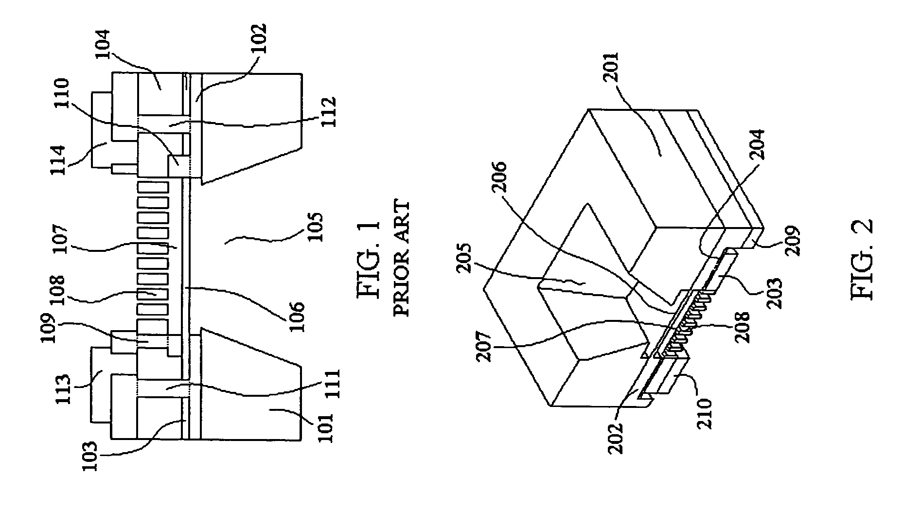
[0034] A typical prior art micromachined capacitive microphone, as shown in FIG. 1, comprises an acoustic cavity 105, a 1-3 μm thick flexible plate 106, a 3-5 μm thick air gap 107, a 10-20 μm thick stiff and perforated plate 108, a first insulating trench couple 109 and 110, a second insulating trench couple 111 and 112, and an electrode couple 113 and 114. The flexible plate 106, the stiff and perforated plate 108, and the air gap 107 form a parallel plate capacitor.

[0035] As can be seen from FIG. 1, the flexible plate 106 is made from a SOI (single crystal silicon on insulator) wafer, which consists of a thick single crystal silicon substrate 101, a thin insulation layer 102, and a thin single crystal silicon layer 103. To complete the capacitor, a polysilicon layer 104 and a sacrificial layer are added to the top of the SOI wafer. The stiff and perforated plate is made up of the polysilicon layer 104 and released by etching of a portion of the sacrificial layer. The remained por...


PUM


Abstract

A single crystal silicon micromachined capacitive microphone is disclosed. The microphone comprises a flexible plate made from a bottom layer of a first epitaxial single crystal silicon layer, a stiff and perforated plate made from a portion of a second epitaxial single crystal silicon layer, a supporting frame is made from a combination of lateral overgrowth of the first epitaxial single crystal silicon layer and a polysilicon layer grown or deposited on the surface of an insulating layer, and an air gap is formed by etching a portion of the first epitaxial single crystal silicon layer. Both the first epitaxial single crystal silicon layer and the second epitaxial single crystal silicon layer are developed from a single crystal silicon substrate. A micromaching technology based on selective formation and etching of porous single crystal silicon layers is used to make the microphone structure.

Description

FIELD OF THE INVENTION [0001] This invention relates generally to a micromachined capacitive microphone and method and more particularly to a single crystal silicon micromachined microphone in which the capacitive elements are all made up of two epitaxial single crystal silicon layers developed from a single crystal silicon substrate. BACKGROUND OF THE INVENTION [0002] Microphones or acoustic transducers are widely employed in a variety of consumer products and specialty instruments such as telephone sets, tape-recorders, video cameras, speech amplifiers and hearing aids. Silicon micro-electro-mechanical-system (MEMS) technology has been used to produce a variety of microphones, which are based on the principle of a variable capacitance, where one electrode of the capacitor is on a flexible plate and moves in response to an acoustic signal. [0003] A good microphone has several qualities: (I) capable of being processed directly to a PCB using standard automatic pick-and-place equipme...

Claims


Application Information

Patent Timeline
Patent Type & Authority Applications(United States)
IPC IPC(8): H04R25/00H04R9/08H04R11/04
CPCH04R19/005H04R2499/11H04R25/00
Inventor TU, XIANG ZHENG
Owner TU XIANG ZHENG
Learn More