Solenoid air valve

a solenoid air valve and air valve technology, applied in the direction of valve operating means/release devices, magnetic bodies, angiography, etc., can solve the problems of increasing magnetic resistance, failure to achieve sufficient sealing and size reduction, and conventional structure suffers from the following problems, so as to improve the efficiency of magnetic circuit, reduce the driving force, and improve the effect of magnetic efficiency

Active Publication Date: 2006-01-12
OMRON HEALTHCARE CO LTD
View PDF2 Cites 3 Cited by
  • Summary
  • Abstract
  • Description
  • Claims
  • Application Information

AI Technical Summary

Benefits of technology

[0011] The present invention aims to solve the problems of lower driving force and lower efficiency of the magnetic circuit caused when the solenoid air valve is made smaller. From the foregoing, an object of the present invention is to provide a solenoid air valve having a structure allowing improvement in magnetic efficiency by making smaller a gap between a frame and a moving coil.
[0013] According to the solenoid air valve of the present invention, the stop area defining a distance of travel of the moving core in the direction away from the fixed core is provided between the side surface of the moving core and the bobbin, and the frame cover has the opening through which the moving core projects outward. Therefore, a gap (distance) between a surface of the frame cover facing the shaft portion and the side surface of the moving core should only correspond to a distance of clearance in which the moving core can slide. That is, the gap (distance) can be minimized. Consequently, magnetic reluctance between the frame cover and the moving core due to this gap (distance) can be lowered, whereby efficiency of the magnetic circuit can be improved.

Problems solved by technology

The conventional structure, however, suffers from the following problems.
When the packing is brought in direct contact with the moving core and the moving core is made thinner for size reduction, magnetic reluctance is increased and driving force necessary for pressing the packing is lowered, which results in failure in achieving sufficient sealing and reduction in size.
In such a case, magnetic flux M is concentrated in a narrow area around rubber packing 250, which results in increase in magnetic reluctance, lower efficiency of a magnetic circuit, and lowering in the driving force.

Method used


Image

  • Solenoid air valve
  • Solenoid air valve
  • Solenoid air valve

Examples


Embodiment Construction

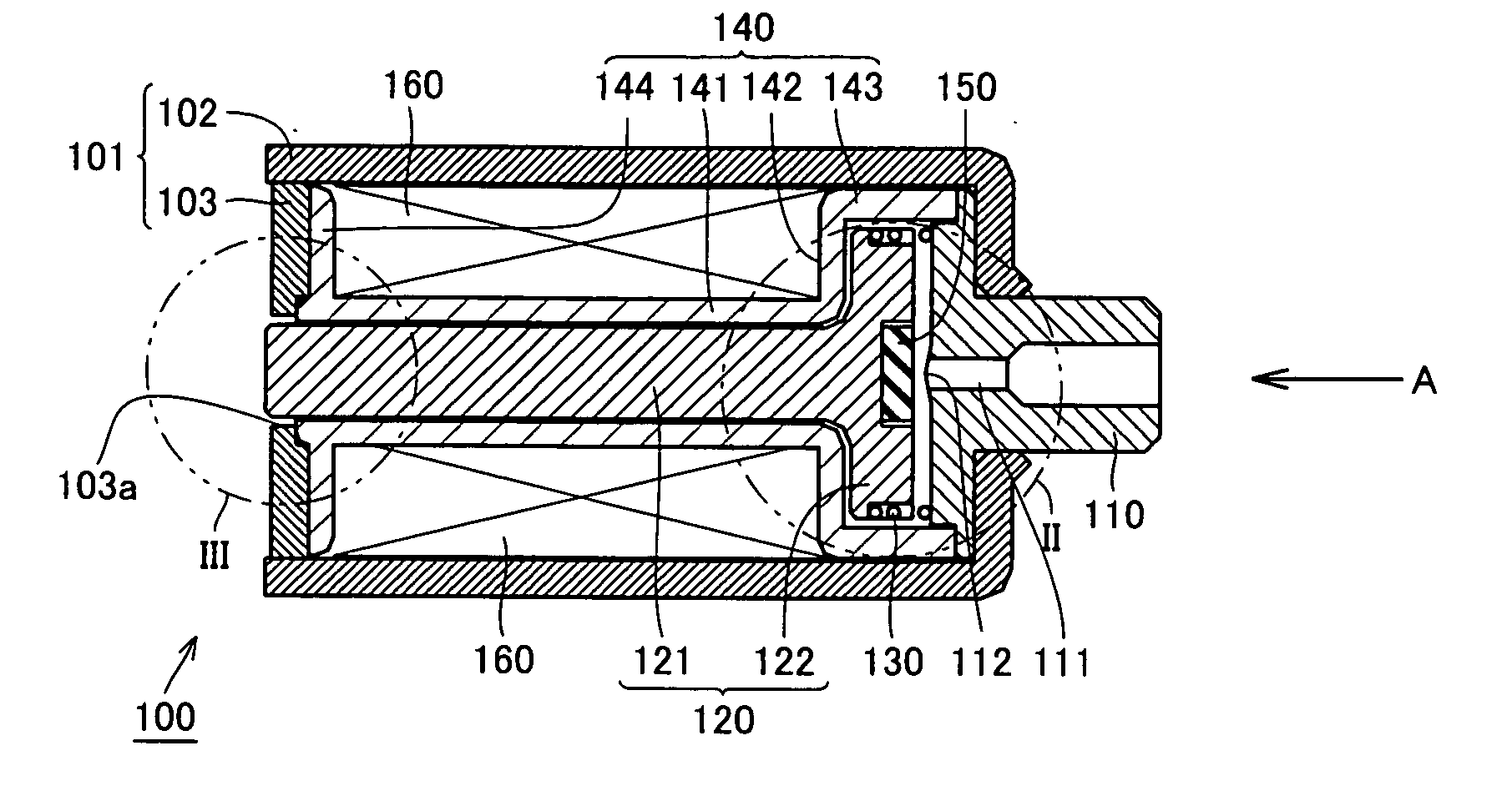
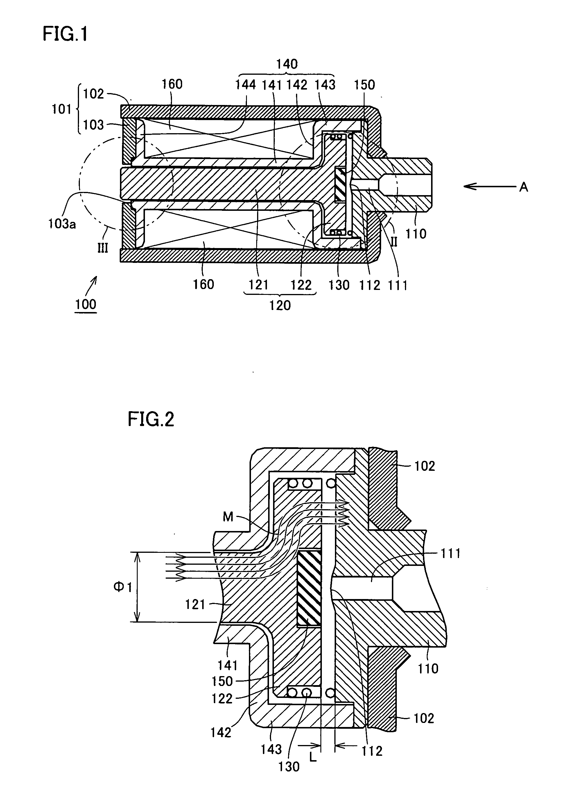
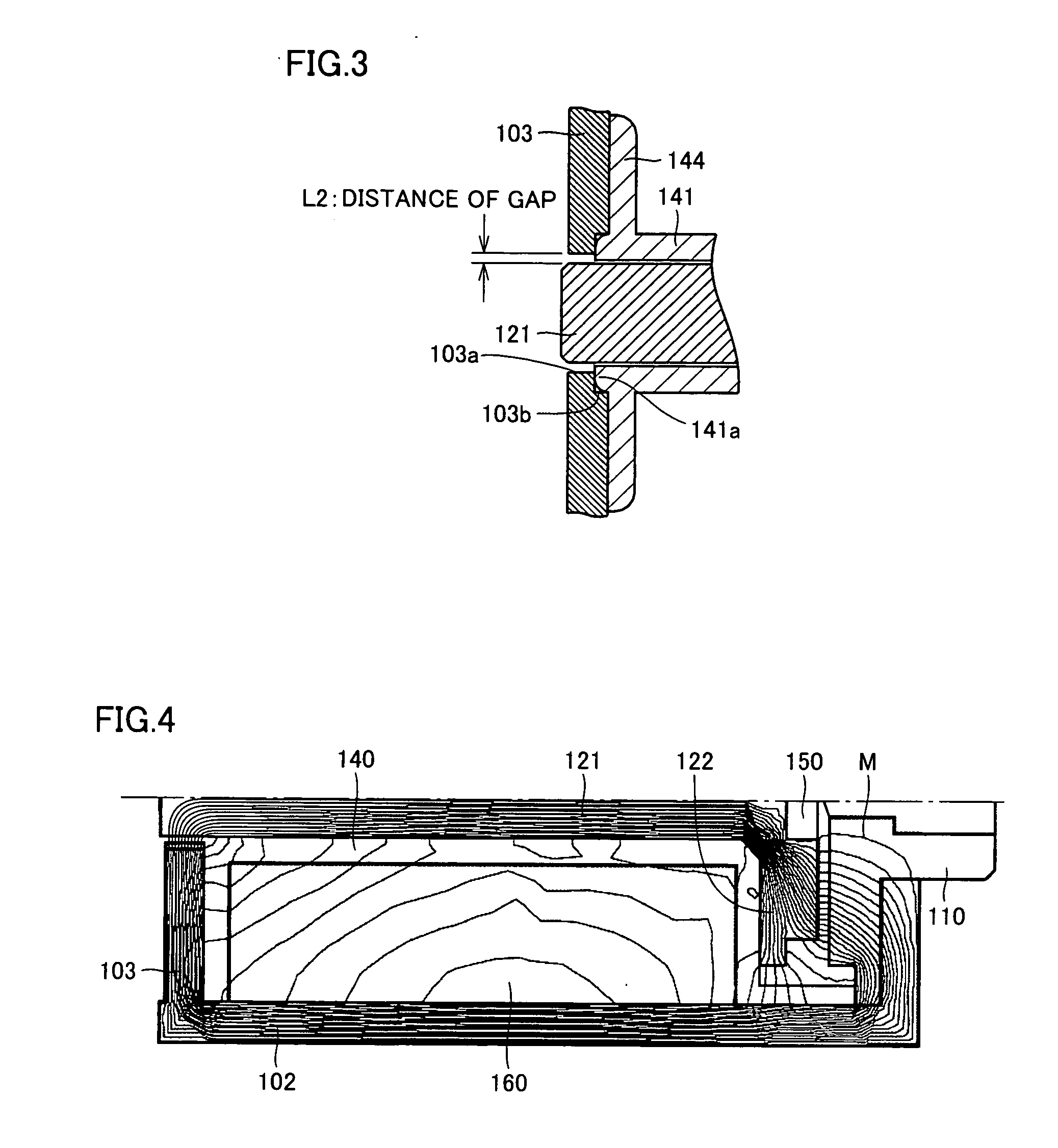
[0025] A structure of a solenoid air valve according to an embodiment of the present invention will be described hereinafter with reference to FIGS. 1 to 3.

[0026] Referring first to FIG. 1, the structure of a solenoid air valve 100 in the present embodiment will be described. Solenoid air valve 100 includes a frame 101 made of a magnetic material. Frame 101 has a frame main body 102 and a frame cover 103 covering one end portion. For example, SUYB-1 (electromagnetic steel) or the like is used as a magnetic material for frame main body 102 and frame cover 103. A fixed core 110 is fixed and adhered to the inside of frame main body 102 on the other end side, such that a part of the fixed core projects outward. An air passage 111 is provided in fixed core 110, and a convex nipple (air outlet) 112 is provided at a position of fixed core 110 opposed to a moving core 120 which will be described later. In addition, frame main body 102 houses moving core 120 accommodated in a bobbin 140 mad...


PUM


Abstract

According to a solenoid air valve, a flange portion of a moving core and a flange portion area of a bobbin implement a stop area defining a distance of travel of the moving core in a direction away from a fixed core. An end portion of a shaft portion of the moving core can project outward through an opening of a frame cover, so that a gap between a surface of the frame cover facing the shaft portion and a side surface of the shaft portion (distance: L2) can be minimized. Consequently, a solenoid air valve having a structure allowing improvement in magnetic efficiency by making smaller the gap between the frame and the moving core is provided.

Description

BACKGROUND OF THE INVENTION [0001] 1. Field of the Invention [0002] The present invention relates to a structure of a solenoid air valve used in a blood pressure monitor or the like. [0003] 2. Description of the Background Art [0004] Blood pressure is measured based on information on artery obtained by placing an air bag around human body (brachium, wrist) and inflating the same with air to apply pressure to the human body. When inflated by an air pump, the air bag is closed so as to avoid air leakage. At the time of measurement, deflation control is performed. When the measurement is finished, the inflated air bag needs to be deflated, in order to release the human body from constraint. A solenoid air valve is often used in such a case. A conventional air valve structure is disclosed in Japanese Patent Laying-Open No. 09-135817 (hereinafter, referred to as document 1) and Japanese Patent Laying-Open No. 2000-097364 (hereinafter, referred to as document 2) described below. [0005] Ac...

Claims


Application Information

Patent Timeline
IPC IPC(8): H01F7/08
CPCF16K31/0658A61B5/0235A61B5/022
Inventor SANO, YOSHIHIKOMIYATANI, YASUTAROMATSUDA, HISATOMIKISHIMOTO, HIROSHIKARO, HIROMICHIFUKUI, RYOICHI
Owner OMRON HEALTHCARE CO LTD
Why Eureka
Try Eureka