
High flux, microporous, sieving membranes and separators containing such membranes and processes using such membranes

a technology of sieving membranes and separators, which is applied in the direction of filtration separation, separation processes, water/sewage treatment, etc., can solve the problems of film degradation, facilitate high flux, and achieve high permeant flow indices

Inactive Publication Date: 2006-09-14
UOP LLC
View PDF22 Cites 75 Cited by
  • Summary
  • Abstract
  • Description
  • Claims
  • Application Information

AI Technical Summary

Benefits of technology

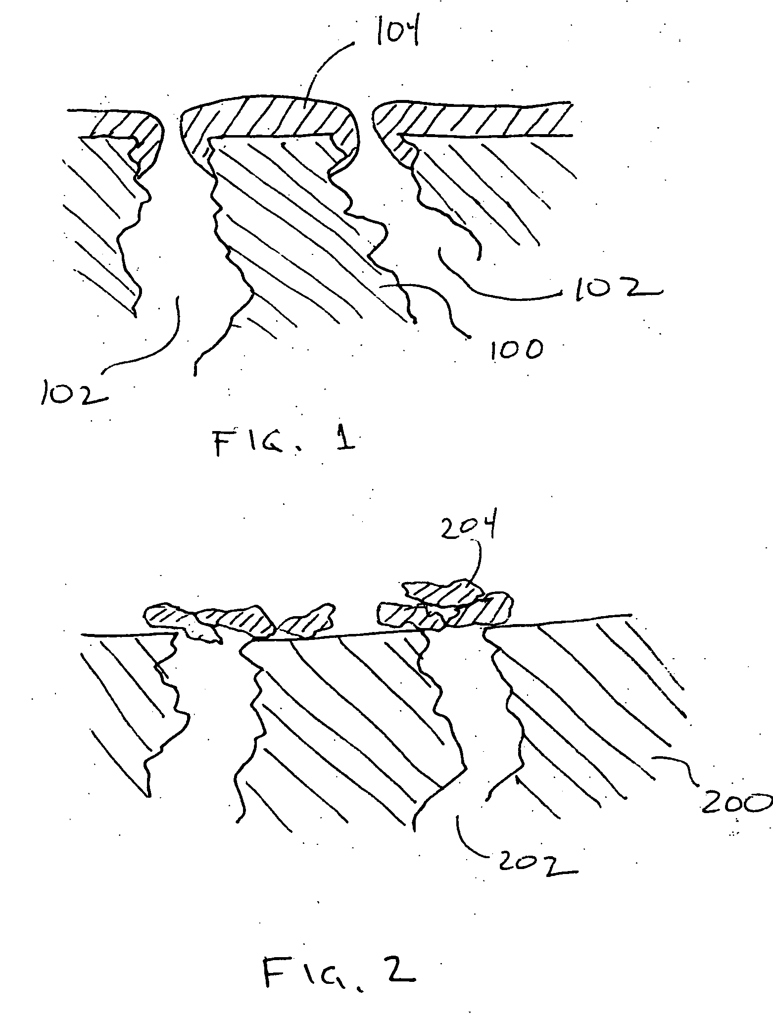
[0049] Without wishing to be limited to theory, the use of nano-sized particles or islands of sieving material facilitate achieving high flux not only because of the small size but also because a traditional membrane barrier film or continuous layer is not extant. Moreover, it is not necessary that a Permeant pass through the entire thickness of the barrier layer. Rather, the Permeant need only pass in and out of channels in the microporous barrier which can be only a fraction of the major dimension of the particle or island. Accordingly high Permeant Flow Indices can be achieved. The advantages of such high Permeant Flow Indices are observable in one or both of reduced membrane surface area and lower driving forces for Permeant recovery as compared to traditional membranes as discussed above.
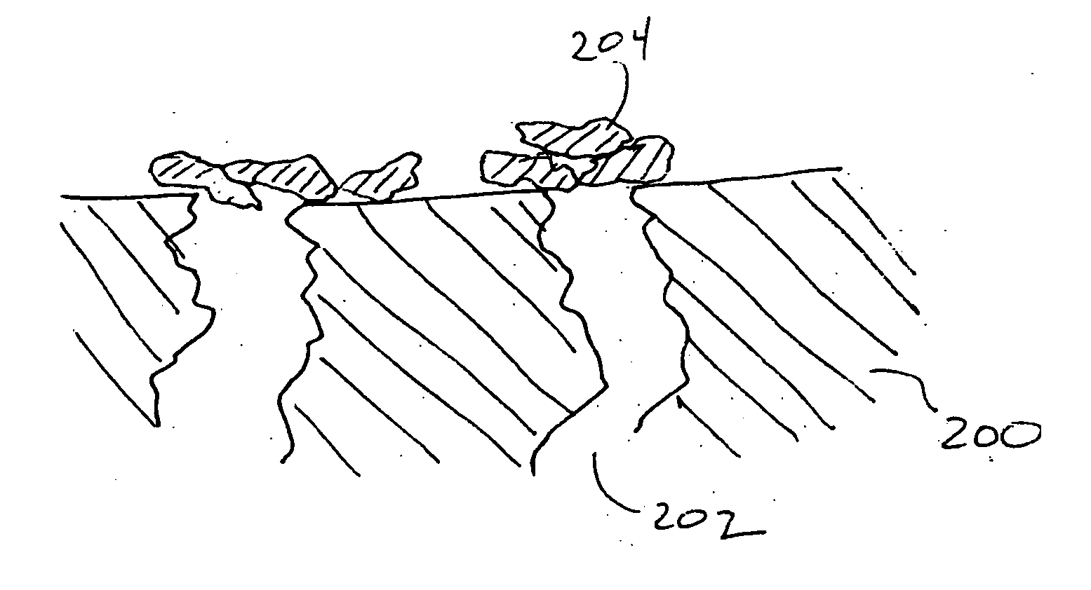
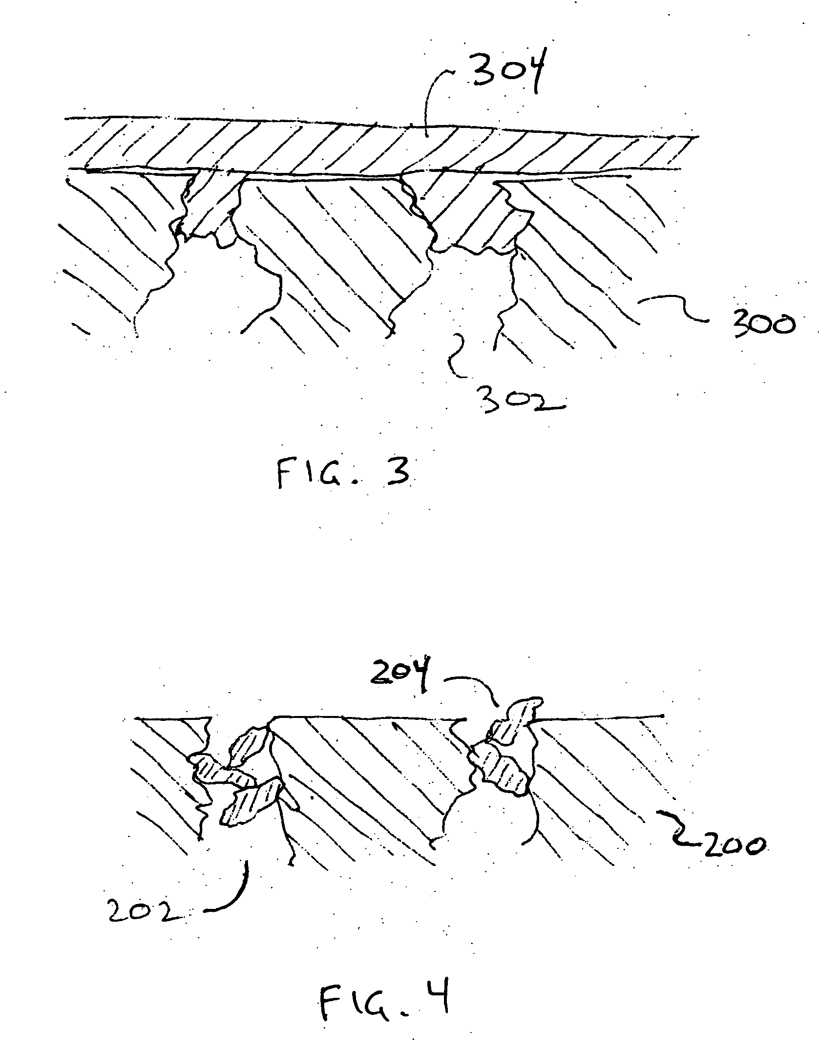
[0051] In this broad aspect of the invention, the discontinuous, microporous barrier is positioned to hinder fluid flow through fluid flow channels defined by the meso / macroporous structure. The barrier may be at least partially occluding the opening of a fluid flow channel of the meso / macroporous structure and / or within the fluid flow channel. Due to the small size of the particles or islands forming the discontinuous assembly of microporous barrier, some selectivity of separation is achievable despite the discontinuity. For a Steric Separation Pair for which separation can be effected by the micropores in the material of the barrier, the Permeant Flow Ratio is preferably at least about 1.1:1, more preferably at least about 1.25:1, and sometimes between about 1.35:1 and 8:1. Advantageously, the membranes of this invention can achieve even higher Permeant Flow Ratios by at least partially occluding at least a portion of the voids between molecular sieve barrier and between molecular sieve barrier and the material of the meso / macroporous structure with which the molecular sieve barrier is associated.

Problems solved by technology

With membrane films such as zeolitic films, differences in thermal expansion between the film and support lead to degradation of the film.

Method used


Image

  • High flux, microporous, sieving membranes and separators containing such membranes and processes using such membranes
  • High flux, microporous, sieving membranes and separators containing such membranes and processes using such membranes
  • High flux, microporous, sieving membranes and separators containing such membranes and processes using such membranes

Examples


Embodiment Construction

[0065] The high flux membranes of this invention can be obtained using a wide variety of techniques and may have different constructions. One type of sieving membrane in accordance with this invention has a discontinuous microporous barrier. In other aspects of this invention, the key feature of the membrane is high flux, even at low selectivities, regardless of whether or not the barrier is discontinuous or continuous. In either, a microporous barrier is used.

[0066] The microporous barrier may be formed by reducing the pore size of an ultrafiltration membrane (effective pore diameters of 1 to 100 nanometers) or a microfiltration membrane (effective pore diameters of 100 to 10,000 nanometers) by, e.g., organic or inorganic coating of the channel either interior of the surface, or preferably, at least partially proximate to the opening of the channel. These types of sieving membranes will be discussed in further detail in another portion of this description.

[0067] Other techniques ...


PUM

PropertyMeasurementUnit
thicknessaaaaaaaaaa
Intrinsic Permeation Thicknessaaaaaaaaaa
surface areaaaaaaaaaaa

Abstract

A sieving membrane comprises a thin, microporous barrier to provide a high flux. The membrane structure can tolerate defects yet still obtain commercially-attractive separations.

Description

CROSS-REFERENCE TO RELATED APPLICATIONS [0001] This application claims priority from Provisional Application Ser. Nos. 60 / 661,087, 60 / 660,958, 60 / 660,959, 60 / 661,086, and 60 / 661,247 all filed Mar. 11, 2005, the contents of which are all hereby incorporated by reference.FIELD OF THE INVENTION [0002] This invention pertains to high flux membranes using microporous barriers to effect rates of passage of molecules therethrough and separators containing such membranes and processes for using such membranes. BACKGROUND OF THE INVENTION [0003] Membranes have long been proposed as a tool for separating components from gases and liquids. The membranes may be of various types using various transport mechanisms. Several examples to give the breadth of different types of membranes include: [0004] supported liquid membranes in which a component in a fluid mixture complexes with a complexing agent retained within the membrane and is transported to the opposite side of the membrane, wherein the dr...

Claims


Application Information

Patent Timeline
Patent Type & Authority Applications(United States)
IPC IPC(8): B01D61/00
CPCB01D67/0002B01D67/0006B01D67/0039B01D67/0041B01D67/0044B01D67/0046B01D67/0051B01D67/0072B01D69/10B01D69/141B01D71/027B01D71/028B01D71/64C07C7/144C10G31/11C07C15/08C07C9/14B01D2323/40B01D2325/02B01D2325/28Y02P20/582B01D71/021B01D2325/0283B01D61/00
Inventor KULPRATHIPANJA, SANTILIU, CHUNQUINGWILSON, STEPHEN T.LESCH, DAVID A.RICE, LYNN H.SHECTERLE, DAVID J.SHIELDS, DALE J.FREY, STANLEY J.
Owner UOP LLC
Learn More