Direct-current power supply and battery-powered electronic apparatus and equipped with the power supply
a power supply and battery technology, applied in the direction of electric variable regulation, process and machine control, instruments, etc., can solve the problems of undershooting of output voltage, unfavorable design changes, and undesirable efficiency reduction, so as to reduce the occurrence of excessive undershooting, reduce the effect of conduction loss, and small circuit siz
- Summary
- Abstract
- Description
- Claims
- Application Information
AI Technical Summary
Benefits of technology
Problems solved by technology
Method used
Image
Examples
embodiment 1
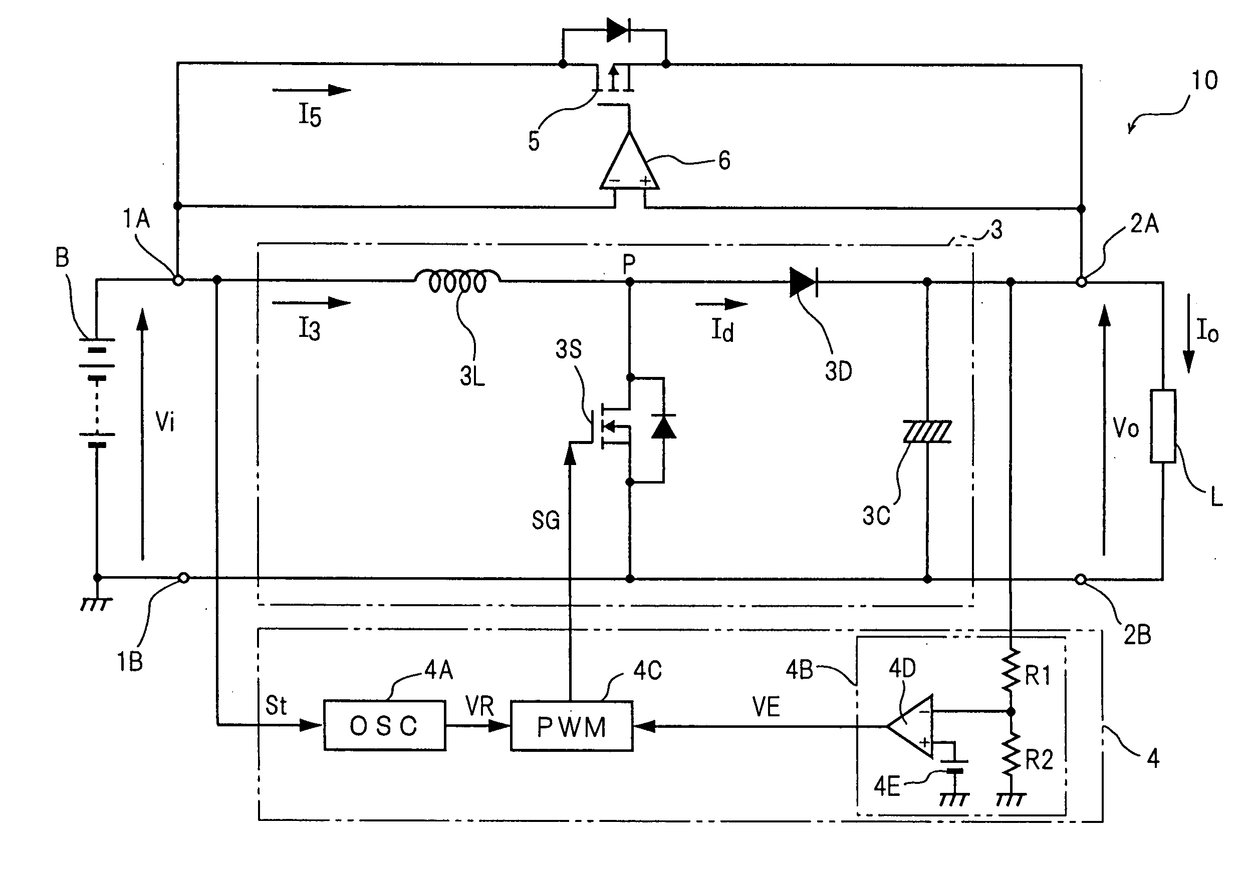
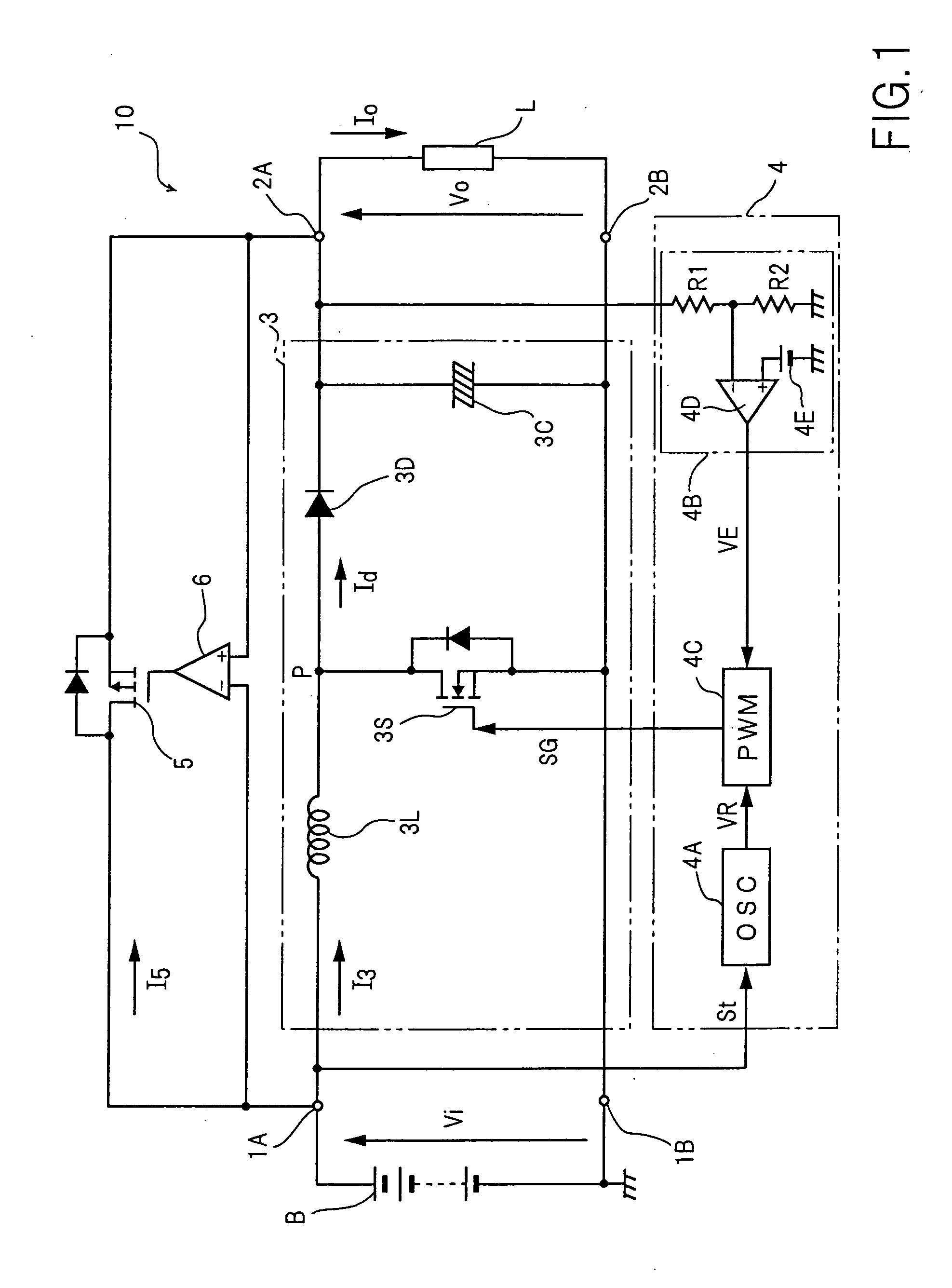
[0119]FIG. 1 is the circuit diagram of the direct-current power supply 10 according to Embodiment 1 of the present invention. Input terminals 1A and 1B of the direct-current power supply 10 are connected to the high- and low-side terminals of a battery B, respectively. Here, the battery B is preferably a rechargeable battery, and further preferably, a lithium ion rechargeable battery. A high side output terminal 2A and a low side output terminal 2B of the direct-current power supply 10 are connected to the high- and low-side terminals of an external load L, respectively. Here, the external load L is another circuit inside the battery-powered electronic appliance, and preferably, includes a power amplifier section in a wireless transmitter section.
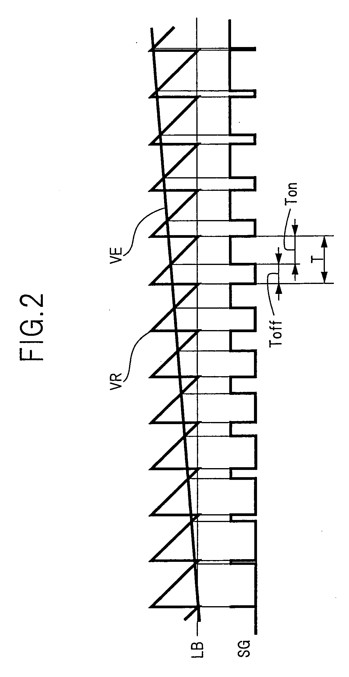
[0120] The direct-current power supply 10 converts an input voltage applied from the battery B, that is, a battery voltage Vi into an output voltage Vo applied to the external load L, and maintains the output voltage Vo at the level equal ...
embodiment 2
[0149]FIG. 4 is the circuit diagram of a direct-current power supply 20 according to Embodiment 2 of the present invention. The direct-current power supply 20 includes components similar to components of the direct-current power supply 10 according to Embodiment 1 shown in FIG. 1. Accordingly, in FIG. 4, the similar components are marked with the same reference symbols as the reference symbols shown in FIG. 1. Furthermore, for the details of the similar components, the description about Embodiment 1 is cited.
[0150] The direct-current power supply 20 according to Embodiment 2 of the present invention comprises an input voltage detecting section 7 in contrast to the direct-current power supply 10 according to Embodiment 1. The input voltage detecting section 7 monitors the battery voltage Vi. When the battery voltage Vi falls, for example, from the initial voltage (cf. the point A shown in FIG. 3A) to a predetermined level, (hereafter, a start input voltage Ei,) the input voltage det...
embodiment 3
[0160] A direct-current power supply according to Embodiment 3 of the present invention comprises circuitry in common with the direct-current power supply 20 according to Embodiment 2 shown in FIG. 4. Accordingly, FIG. 4 is referred to for the circuitry, and the description about Embodiment 2 is cited for the details of the common part.
[0161] The direct-current power supply according to Embodiment 3 of the present invention is different from the direct-current power supply 20 according to Embodiment 2 in the following ways. First, the input voltage detecting section 7 sets the start input voltage Ei at the lowest equal to the sum of the non-operating output lower limit Ec and the maximum voltage drop Vonmax: Ei≧Ec+Vonmax. Next, the PWM circuit 4C sets a lower limit Tonmin to be reckoned with (hereafter, a minimum ON width), for the ON time Ton of the chopper switch 3S. Thereby, a lower limit rmin=Tonmin / T is provided for the duty ratio r=Ton / T (T: the switching period). Accordingly...
PUM
 Abstract
Description
Claims
Application Information
 - R&D
- Intellectual Property
- Life Sciences
- Materials
- Tech Scout
- Unparalleled Data Quality
- Higher Quality Content
- 60% Fewer Hallucinations
Browse by: Latest US Patents, China's latest patents, Technical Efficacy Thesaurus, Application Domain, Technology Topic, Popular Technical Reports.
© 2025 PatSnap. All rights reserved.Legal|Privacy policy|Modern Slavery Act Transparency Statement|Sitemap|About US| Contact US: help@patsnap.com


