
Dishwasher filter system

a filter system and dishwasher technology, applied in the direction of cleaning using liquids, washing/rinsing tableware, house cleaners, etc., can solve the problems of increasing hot water and energy consumption

Inactive Publication Date: 2006-01-12
WHIRLPOOL CORP
View PDF5 Cites 73 Cited by
  • Summary
  • Abstract
  • Description
  • Claims
  • Application Information

AI Technical Summary

Benefits of technology

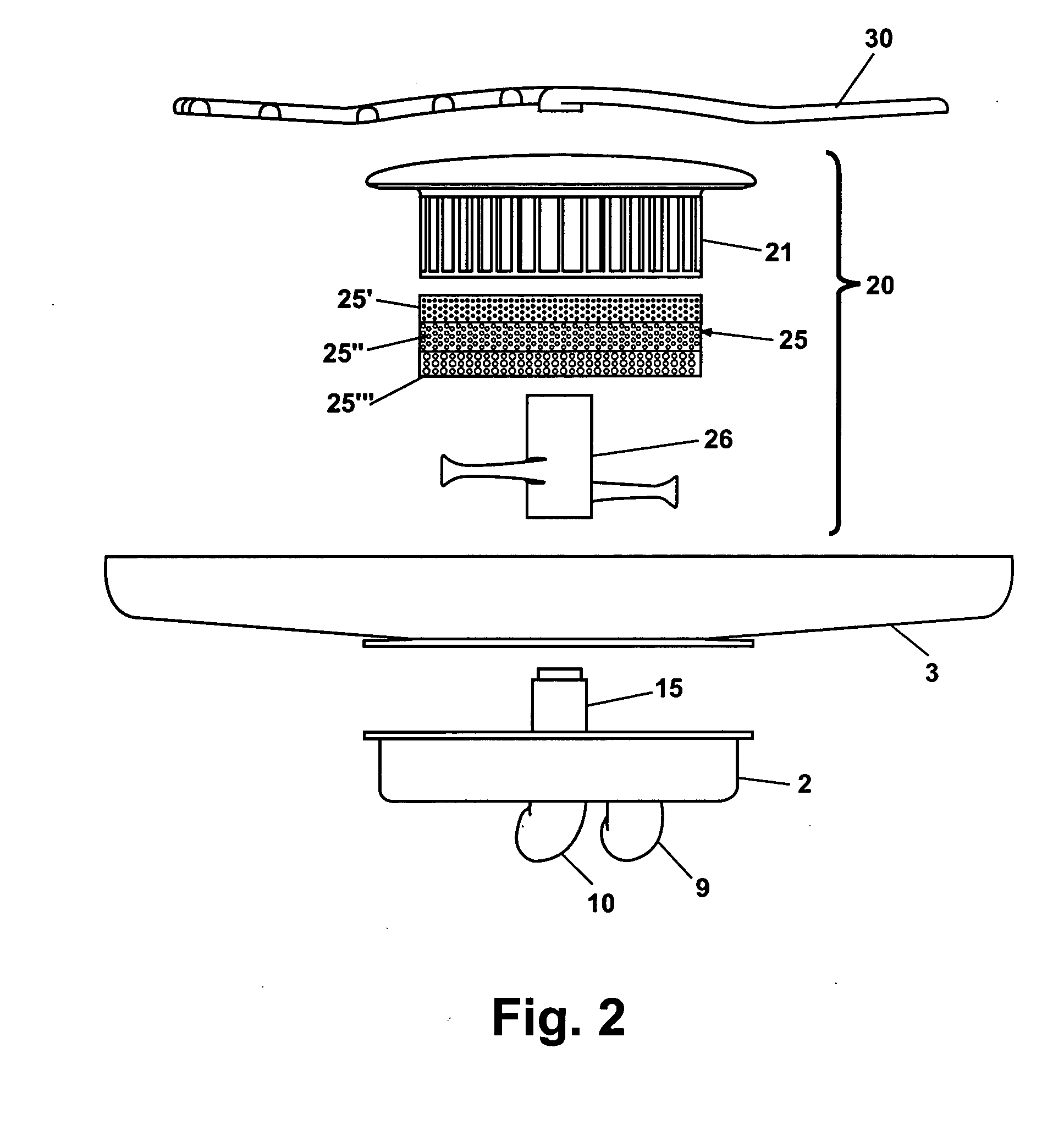
The invention is a dishwasher with a filter system positioned in the sump of the dishwasher. The filter system includes a vertical filter retainer and an overlying perforate hood carrying a multiple porosity filter element. The filter element has openings that vary in size from the top to the bottom. The filter element can have three vertically arranged bands of differing porosity openings with the top band having fine porosity openings, the middle band having medium porosity openings, and the bottom band having coarse porosity openings. The perforate hood can have openings with porosity equal to or greater than the most porous openings in the filter element. The dishwasher can also have a control and sensor to detect accumulation of soil particles on the filter element and activate the drain pump to remove soil particles when a predetermined accumulation is detected. The dishwasher can also have a floor and plurality of walls, a wash pump, a drain pump, and a sump in the floor with a mounting cavity for the wash pump and drain pump. The spray arm can have S shaped arms and a plurality of nozzles configured to spray water in multiple directions. The drain pump can have a soil management system positioned to comminute soil particles prior to entry into the drain pump after the soil particles leave the sump.

Problems solved by technology

A disadvantage of multiple flushing cycles is increased hot water and energy usage.

Method used


Image

  • Dishwasher filter system
  • Dishwasher filter system
  • Dishwasher filter system

Examples


Embodiment Construction

[0032] The filter assembly according to the invention can be used in a compact drawer dishwasher configuration. While the invention will be described in the context of drawer dishwasher configuration embodiments, those skilled in the art will understand that the filter assembly according to the invention could be used in a front loading tank configuration as well as in a drawer configuration.

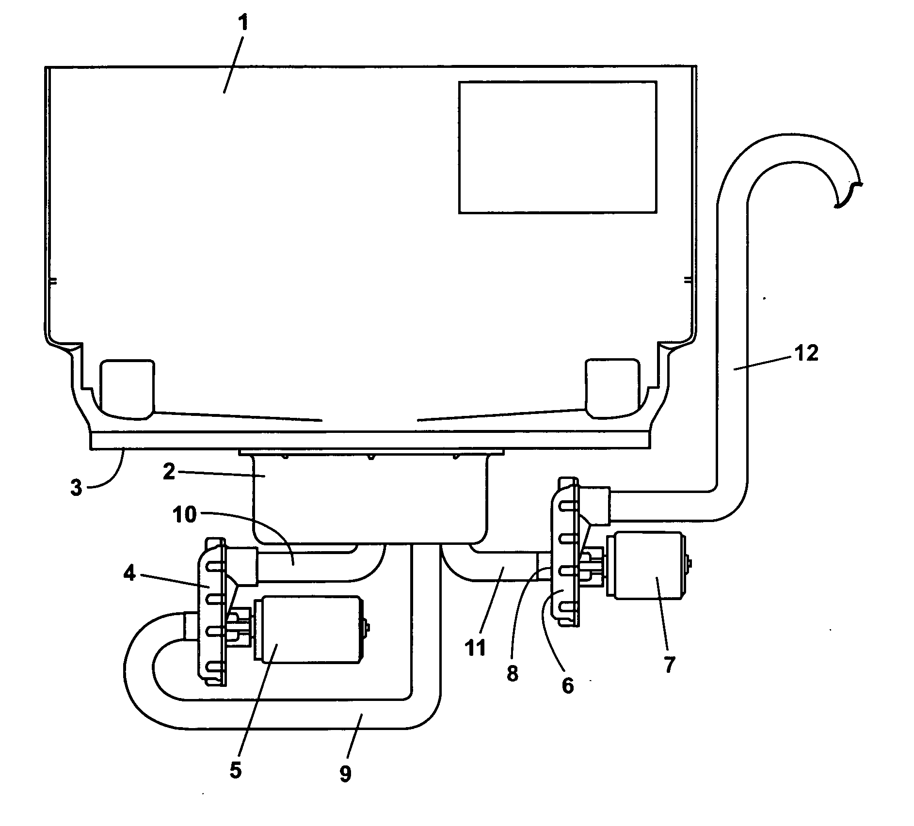
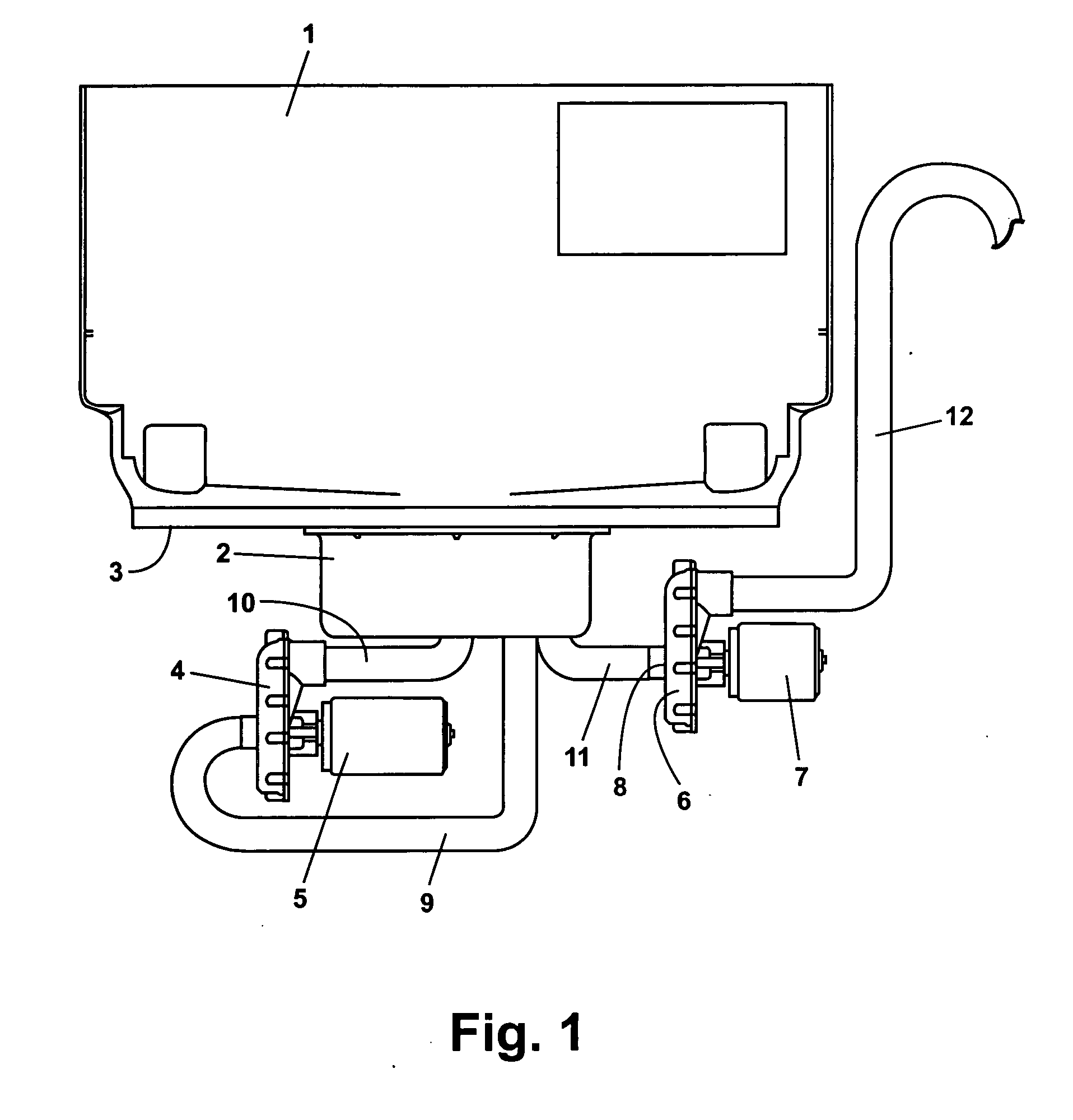
[0033] Turning to FIG. 1, a tank 1 can have a sump 2 positioned on the bottom wall 3 for a drawer configuration dishwasher. A filter assembly according to the invention can be located in the sump 2. A wash pump 4 can have a wash pump motor 5. A drain pump 6 can have a drain pump motor 7. A soil management system 8 can be located in the inlet of drain pump 6. Soil management system 8 will be described in further detail below. Water being recirculated by the wash pump 4 can flow from sump 2 via wash pump inlet conduit 9 and can flow from wash pump 4 back to the sump 2 via wash pump outlet conduit...


PUM


Abstract

A filter system for dishwasher with a sump having inlets leading to a wash pump and a drain pump in the bottom wall. The filter assembly includes a vertical filter retainer an overlying perforate hood, a multiple porosity filter element carried on the filter retainer and a back wash sprayer rotatably mounted inside the filter retainer with at least one backwash nozzle directed toward the filter assembly. The inlet leading to the wash pump is positioned inside the filter element and the inlet to the drain pump is located outside the filter element. The filter element has openings that vary in size from the top to the bottom of the filter element. The filter element openings can be arranged in bands of different porosity openings including fine, medium and coarse porosity openings. The perforate hood can have coarse porosity openings.

Description

BACKGROUND OF THE INVENTION [0001] 1. Field of the Invention [0002] The invention relates to a micron filter system for a dishwasher having a wash pump and a drain pump. [0003] 2. Description of the Related Art [0004] Dishwashers have filters to reduce the amount of food particles recirculated and potentially re-deposited on dishes being washed. Prior art dishwasher filter configurations have employed micron filters to improve cleaning performance of the dishwasher. Typically, such micron filters are bypass filters in which only a portion of the wash water being recirculated in the dishwasher during wash and rinse cycles passes through the micron filter to reduce filter clogging and impaired performance. Another approach to the use of micron filters is to provide frequent flushing of soil particles to drain, again to reduce filter clogging. A disadvantage of multiple flushing cycles is increased hot water and energy usage. SUMMARY OF THE INVENTION [0005] In one aspect of the inventi...

Claims


Application Information

Patent Timeline
Patent Type & Authority Applications(United States)
IPC IPC(8): B08B3/02
CPCA47L15/4206A47L15/4227A47L15/4225A47L15/4208
Inventor GURUBATHAM, VINCENT P.SHARKEY, JOSEPH K.TORBERG, AARON M.ASHTON, ROBERT H.
Owner WHIRLPOOL CORP
Learn More