
Intrusion detection system for use on an optical fiber using a translator of transmitted data for optimum monitoring conditions

Active Publication Date: 2006-01-05
NETWORK INTEGRITY SYST
View PDF1 Cites 19 Cited by
  • Summary
  • Abstract
  • Description
  • Claims
  • Application Information

AI Technical Summary

Benefits of technology

[0033] Using adaptive filtering, normal background disturbances from heating / cooling systems, motors, fans and other building systems can be learned and filtered out. This will allow maximum sensitivity to intrusion attempt signatures while minimizing the probability of false alarm events. The design objective is to identify intrusion attempts while the attack is still at the outer layer of the cable structure. This will allow for rapid location and interception of any intruder.

Problems solved by technology

However, this adds to the complexity of the network.
Current IDSs are hampered by a Base-Rate Fallacy limitation, which is the inability to suppress false alarms.
Additionally, software-based IDSs do not protect against passive optical fiber tapping, which can go undetected by the network hardware.
This causes a small spatial distortion in the core / cladding guiding properties and a fraction of the light escapes the fiber.
This results in a loss of received optical power of only 0.04 or 0.004 dBm and is impossible to detect reliably by power measurement methods.

Method used


Image

  • Intrusion detection system for use on an optical fiber using a translator of transmitted data for optimum monitoring conditions
  • Intrusion detection system for use on an optical fiber using a translator of transmitted data for optimum monitoring conditions
  • Intrusion detection system for use on an optical fiber using a translator of transmitted data for optimum monitoring conditions

Examples


Embodiment Construction

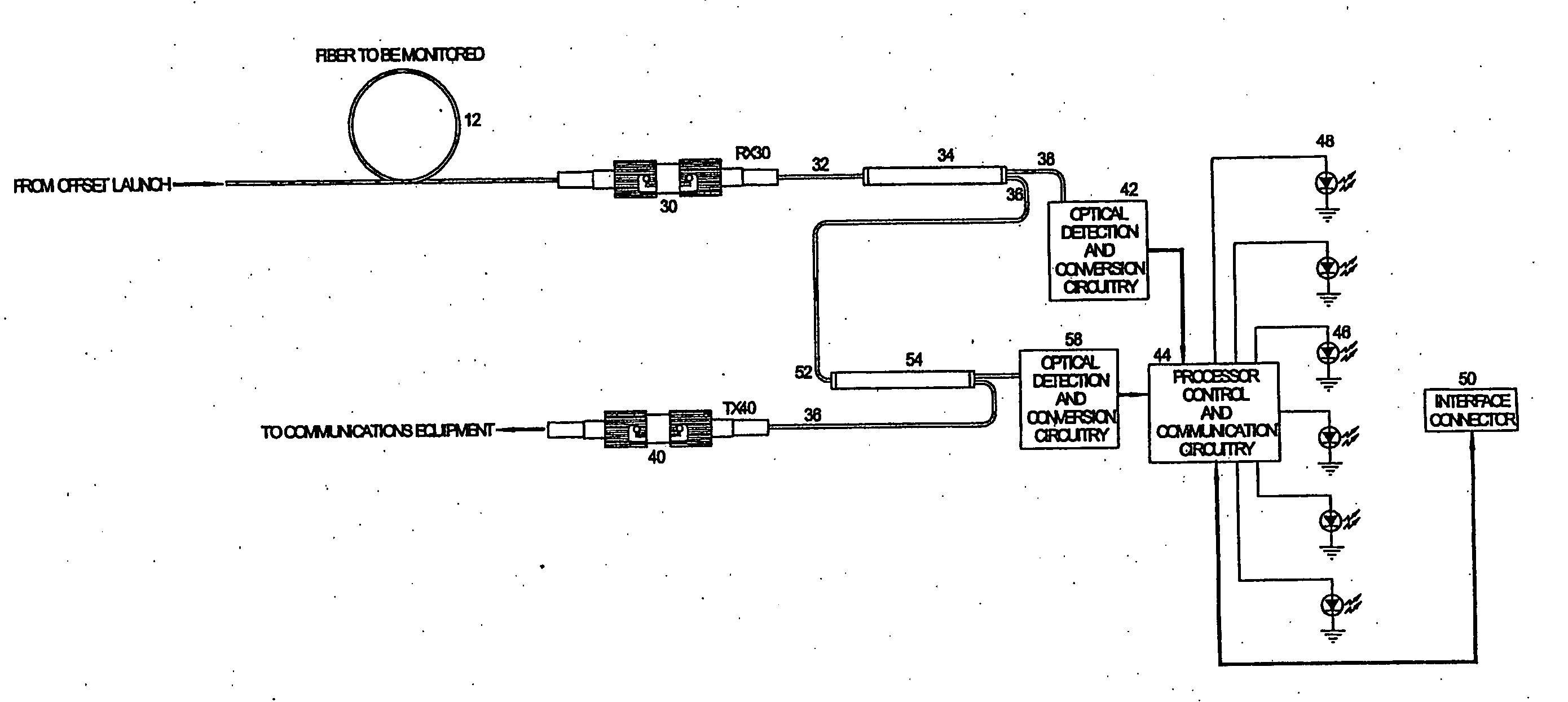
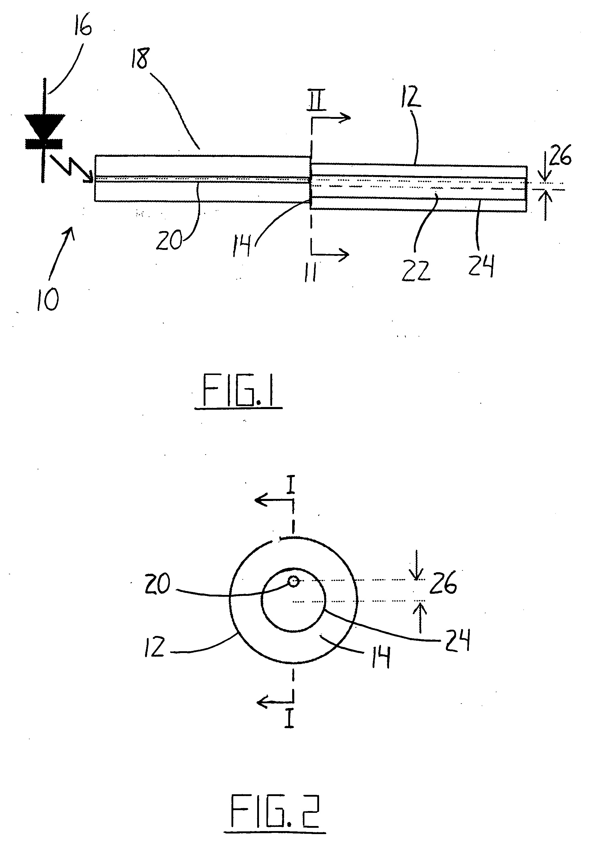
[0043] Referring to the accompanying drawings, and particularly to FIGS. 1 and 2, a transmitter 10 is illustrated for setting up a narrow spectral width, under-filled, non-uniform mode field power distribution in a multimode optical fiber 12. With this type of mode field, the power distribution in the higher order modes changes with physical disturbance of the fiber, despite the absence of any power loss caused by the disturbance.

[0044] The non-uniform high order mode field may be set up in the multimode fiber 12 by illuminating the proximal (near) or transmit end 14 of the fiber with a point source of light that is offset from the center of the optical fiber core. This can be accomplished by a using a laser, optical lenses and positioning mechanics. In the illustrated embodiment, however, this is accomplished more simply by launching a laser 16 into a short length of single mode fiber 18 spliced to the multimode fiber with the center of its core 20 offset from the center of the co...


PUM


Abstract

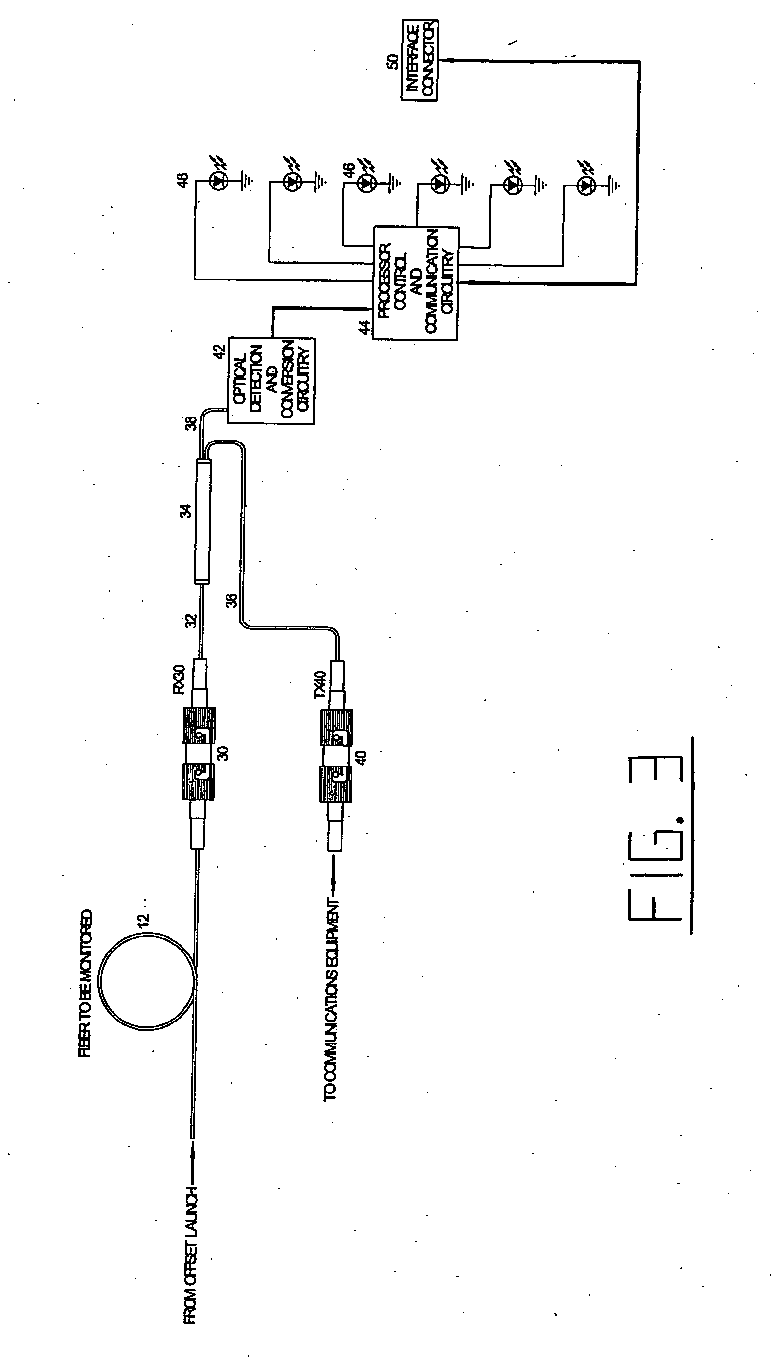
A method and system of intrusion detection system for a multimode fiber optic cable. A light signal is launched into the cable fiber to establish a narrow spectral width, under-filled non-uniform mode field power distribution in the cable. A small portion of the higher order signal modes arriving at the remote end of the cable is sampled by use of a coupler and monitored for transient changes in the mode field power distribution. The power distribution changes with physical disturbance of the cable. When those changes are detected as being characteristic of fiber intrusion, the system activates an alarm. This method can sense and alarm any attempt to access the optical fibers in a fiber optic communication cable. In preferred embodiments, the active signal of a multimode optical fiber is monitored for both signal degradation and transient power disturbance patterns that could indicate fiber damage or physical intrusion. A translator can be provided in an existing optical fiber system in which the data signals are translated in wavelength and / or launch conditions to optimize the monitoring signals in an otherwise non-optimized system.

Description

[0001] This application is a continuation-in-part application of PCT Application PCT / US2004 / 021268 filed 02 Jul. 2004. [0002] This application claims the benefit of the priority date under 35USSC119 from Provisional Application 60 / 488,374 filed 18 Jul. 2003. [0003] Reference is made to a co-pending application filed on the same date as this application by the same inventors, which is Application Ser. No. (not yet known) attorney docket number 85570-602 entitled AN INTRUSION DETECTION SYSTEM FOR USE ON AN OPTICAL FIBER USING A TRANSLATOR OF TRANSMITTED DATA FOR OPTIMUM MONITORING CONDITIONS.FIELD OF THE INVENTION [0004] The present invention relates to the detection of physical intrusion into a optical fiber. BACKGROUND OF THE INVENTION [0005] Gigabit Ethernet multimode fiber optic backbone cables are being deployed to connect sections of high-speed networks together. To secure these high-speed networks, software based Intrusion Detection Systems (IDSs) have been introduced. These sy...

Claims


Application Information

Patent Timeline
IPC IPC(8): G02B6/00G02B6/44
CPCG02B6/262H04B10/0771G02B6/4469G02B6/00G02B6/42
Inventor VOKEY, DAVID E.BRIDGES, MARK K.MURPHY, CARY R.
Owner NETWORK INTEGRITY SYST
Learn More