
Method for producing coils and coil circuits

a technology of coils and circuits, applied in the manufacture of stators/rotor bodies, magnets, magnetic bodies, etc., can solve the problems of high degree of wiring complexity at the end of windings, and the ability of threading to permit only a low slot space factor

Inactive Publication Date: 2006-01-05
ROBERT BOSCH GMBH
View PDF3 Cites 23 Cited by
  • Summary
  • Abstract
  • Description
  • Claims
  • Application Information

AI Technical Summary

Benefits of technology

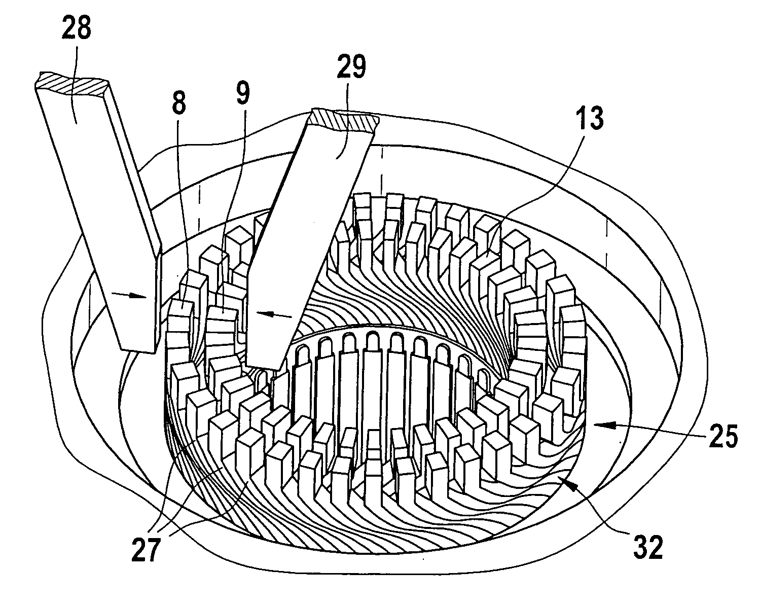
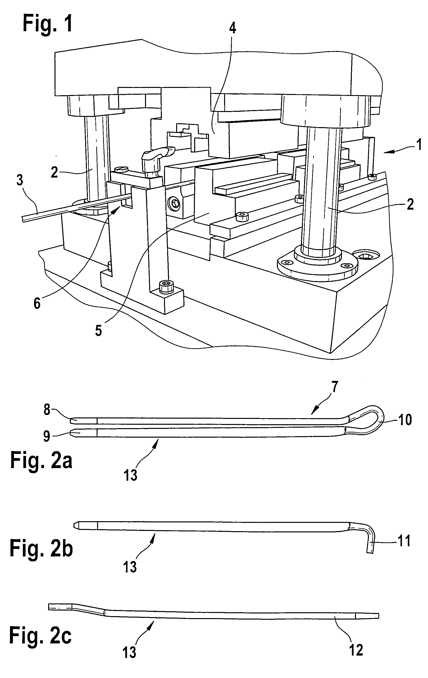
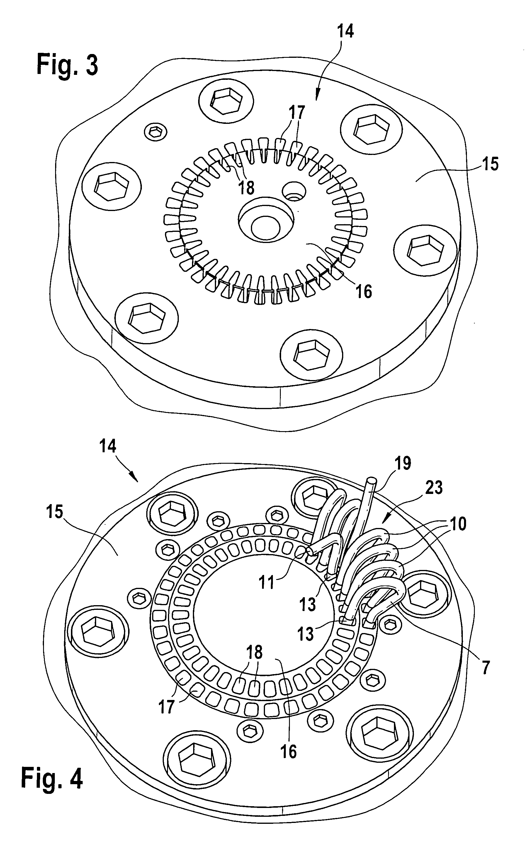
[0008] The method proposed according to the present invention for manufacturing 3-phase windings with interconnection can be used to achieve high slot space factors, which can only be achieved to a limited degree using the threading technique. Due to the high slot space factors that can be achieved, it is possible to reduce the structural volume of 3-phase windings produced using the method according to the present invention. Moreover, using the method proposed according to the present invention, makes it possible to achieve an automatable manufacture of the windings. Integrally joining the interconnection of the star point to one side of a stator of an electric machine makes it possible to eliminate the previously required separate, manually executed work steps when manufacturing 3-phase windings. The interconnection of the star point can be integrated into the manufacture of the 3-phase windings, thus permitting the achievement of an automatable manufacture of the winding on the one hand and an automatable manufacture of the star point during the same manufacturing process on the other.

Problems solved by technology

But producing windings for low-voltage motors, e.g. asynchronous motors, out of parallel individual wires results in a high degree of wiring complexity at the ends of the winding, which is generally manufactured by hand.
The windings for asynchronous motors manufactured out of parallel wires using the threading technique also have the disadvantage that the threading technique permits only a low slot space factor to be achieved.

Method used


Image

  • Method for producing coils and coil circuits
  • Method for producing coils and coil circuits
  • Method for producing coils and coil circuits

Examples


Embodiment Construction

[0008] The method proposed according to the present invention for manufacturing 3-phase windings with interconnection can be used to achieve high slot space factors, which can only be achieved to a limited degree using the threading technique. Due to the high slot space factors that can be achieved, it is possible to reduce the structural volume of 3-phase windings produced using the method according to the present invention. Moreover, using the method proposed according to the present invention, makes it possible to achieve an automatable manufacture of the windings. Integrally joining the interconnection of the star point to one side of a stator of an electric machine makes it possible to eliminate the previously required separate, manually executed work steps when manufacturing 3-phase windings. The interconnection of the star point can be integrated into the manufacture of the 3-phase windings, thus permitting the achievement of an automatable manufacture of the winding on the o...


PUM

PropertyMeasurementUnit
Angleaaaaaaaaaa
Shapeaaaaaaaaaa

Abstract

The present invention relates to a method for manufacturing multiphase windings (32) of an electric machine, in which the following process steps are carried out. Cross-sectional profiles (13) that increase the slot space factor are stamped onto wire elements (7, 11, 12). Offsetting dies (14, 26) are loaded with stamped wire elements (7) to constitute the winding (32), stamped wire elements (11) to constitute an integrated star point (21), and stamped wire elements (12) for supplying current to the winding (32). The offsetting dies (14, 26) offset the stamped wire elements (7, 11, 12) in their end regions. An interconnection of the integrated star point (21) is produced by thermally attaching (30) the stamped wire elements (11) for the integrated star point (21)to a connecting ring (40) on an inside (41) of a finished winding head (20).

Description

PRIOR ART [0001] Windings for electric machines such as asynchronous motors can be manufactured by means of the threading technique. In the manufacture of windings for electric machines, the threading technique is used for low-voltage motors operated at voltages below 50 V and in electric motors operated with higher voltages. When manufacturing windings for low-voltage motors (operating voltage=to 50 V ), the windings are manufactured out of parallel wires in order to assure the required winding cross section. PRIOR ART [0002] Low-voltage motors that are operated with operating voltages below 50 V are used in steering motors for vehicles or for actuators used in vehicles. Electrical systems in motor vehicles today are generally designed as 12 V electrical systems; judging from current development trends, the use of 42 V electrical systems in motor vehicles could conceivably become the new standard. Both electrical system voltages, i.e. an electrical system voltage of 12 V and an ele...

Claims


Application Information

Patent Timeline
IPC IPC(8): H02K17/00H01F7/06H02K15/02H02K15/00H02K15/04
CPCH02K15/0037H02K15/0056H02K15/0081H02K15/0414Y10T29/49009H02K15/064Y10T29/49073Y10T29/49012H02K15/0428
Inventor OSSENKOPP, STEFANERMER, MARTIN
Owner ROBERT BOSCH GMBH
Learn More