
Deck system

a deck and elevated technology, applied in the field of elevated deck systems, can solve the problems of time-consuming and laborious, affecting the maintenance effect of the structure, and the limited configuration of paver stone patios, etc., and achieve the effect of low maintenan

Inactive Publication Date: 2005-12-29
SMITH BRENT A
View PDF28 Cites 20 Cited by
  • Summary
  • Abstract
  • Description
  • Claims
  • Application Information

AI Technical Summary

Benefits of technology

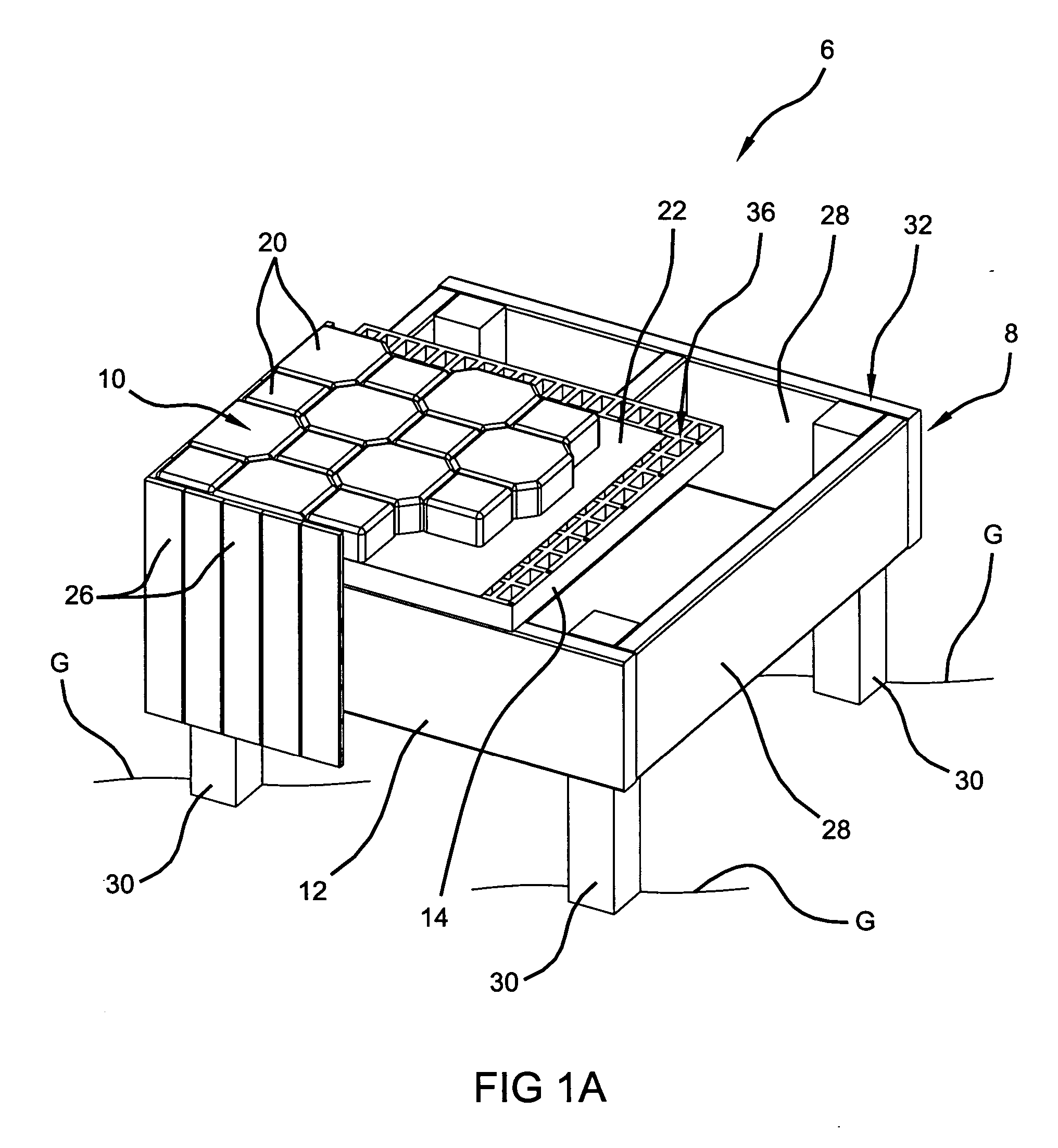
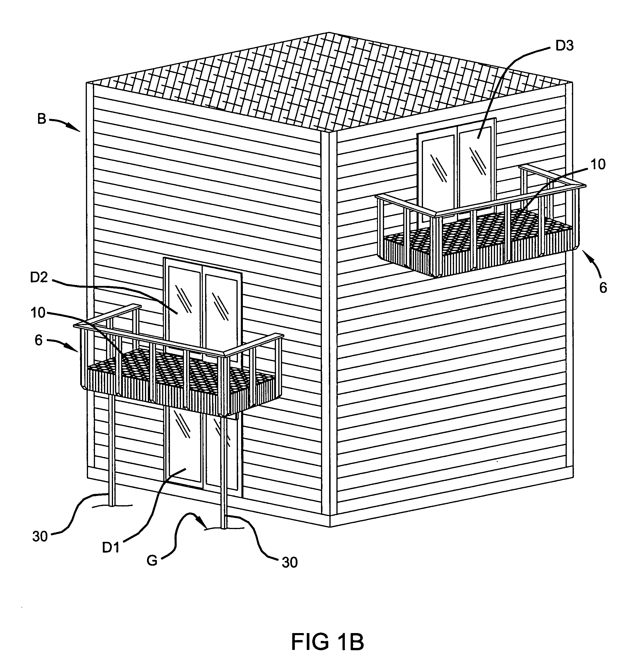
[0009] A deck system includes an interconnected subframe operable to engage a ground surface and provide an elevated substantially horizontal support surface. A subfloor is coupled to the subframe and defines a working surface. A masonry floor surface including a plurality of brick pavers, for example, is disposed on the working surface. The masonry floor surface provides the advantages of durability and low maintenance while the subframe and subfloor allow construction at an elevated location, such as a second story of a home.
[0010] The subframe can comprise wood and have at least one support post extending in a generally vertical orientation between the ground and the horizontal support surface. Also, the subfloor can comprise a plurality of passages defined through the working surface. The subfloor, which may comprise plastic, can include a plurality of recess portions for accepting a fastener head in an installed position. The subfloor provides a high strength-to-weight ratio and is easily workable with conventional woodworking tools. The masonry materials are generally selected from readily available materials, such as brick paving blocks, cultured stone, natural stone, slate, fieldstone, marble and conventional brick. According to other features, the deck system may include a fascia arranged around a perimeter of the deck system. A semi-permeable barrier comprised of a fabric material can be disposed between the subfloor and the plurality of masonry materials to retain sand and enable moisture pass through.

Problems solved by technology

As a result, preparing the ground including digging out portions of dirt and / or adding portions of dirt can become time consuming, costly and labor intensive.
In addition, paver stone patios conventionally have been limited solely to preparation and creation directly on a ground surface.
However, such configurations tend to be cost prohibitive above two feet in elevation.
In many instances, the preparation of the ground surface accounts for a substantial amount of the overall installation time and expense.

Method used


Image

  • Deck system
  • Deck system
  • Deck system

Examples


Embodiment Construction

[0018] The following description of the preferred embodiment(s) is merely exemplary in nature and is in no way intended to limit the invention, its application, or uses.

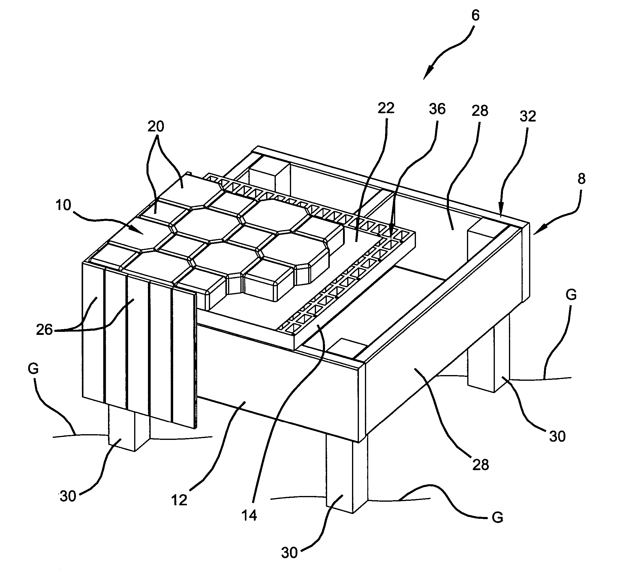
[0019] With initial reference to FIGS. 1A-2, a deck system according to the present teachings is shown and identified generally at reference 6. The deck system 6 generally includes an elevated substructure 8 and a masonry deck surface 10. The elevated substructure 8 includes a subframe 12 and a subfloor 14. The masonry deck surface 10 includes a plurality of paving blocks 20. A semi-permeable barrier 22 is disposed between the subfloor 14 and the paving blocks 20. Fascia segments 26 are arranged around a periphery of the deck system 6.

[0020] As will become appreciated from the discussion herein, the deck system 6 provides an improved alternative to traditional decking or paving block patios. The deck system 6 provides the low maintenance advantages associated with paving blocks while providing a substructure for lo...


PUM


Abstract

A deck system includes an interconnected subframe operable to engage a ground surface and provide an elevated substantially horizontal support surface. A subfloor is coupled to the subframe and defines a working surface. A masonry floor surface including a plurality of brick pavers, for example, is disposed on the working surface. The masonry floor surface provides the advantages of durability and low maintenance while the subframe and subfloor allow construction at an elevated location, such as a second story of a home.

Description

CROSS-REFERENCE TO RELATED APPLICATIONS [0001] This application claims the benefit of U.S. Provisional Application No. 60 / 583421, filed on Jun. 28, 2004. The disclosure of the above application is incorporated herein by reference.FIELD OF THE INVENTION [0002] The present invention relates to decks and more specifically to an elevated deck system supporting a deck surface of masonry materials, such as brick pavers. BACKGROUND OF THE INVENTION [0003] Decks are constructed on buildings to provide additional outdoor floor space for residential and commercial applications. Conventional decks are typically constructed of wood and are adapted to provide some degree of elevation relative to the ground. Often decks are arranged relative to a doorway such that convenient access between the building and the deck may be achieved. In some instances, a doorway may be provided on an upper level of a building whereby a deck is constructed having support structure consisting of vertical posts anchor...

Claims


Application Information

Patent Timeline
Patent Type & Authority Applications(United States)
IPC IPC(8): E04B1/00E04F15/08E04F15/18E04H12/00
CPCE04B1/003E04F15/18E04F15/08
Inventor SMITH, BRENT A.
Owner SMITH BRENT A
Learn More