
Building structure with purlin to beam connection

a technology of purlin and beams, applied in the direction of roofs, towers, buildings, etc., can solve the problems of affecting the quality of construction, labor and time, and consuming substantial amounts of material, and achieve the effect of reducing the amount of high-cost manual and skilled labor, high speed and rapid construction

Inactive Publication Date: 2005-12-29
PORTER WILLIAM H
View PDF22 Cites 11 Cited by
  • Summary
  • Abstract
  • Description
  • Claims
  • Application Information

AI Technical Summary

Benefits of technology

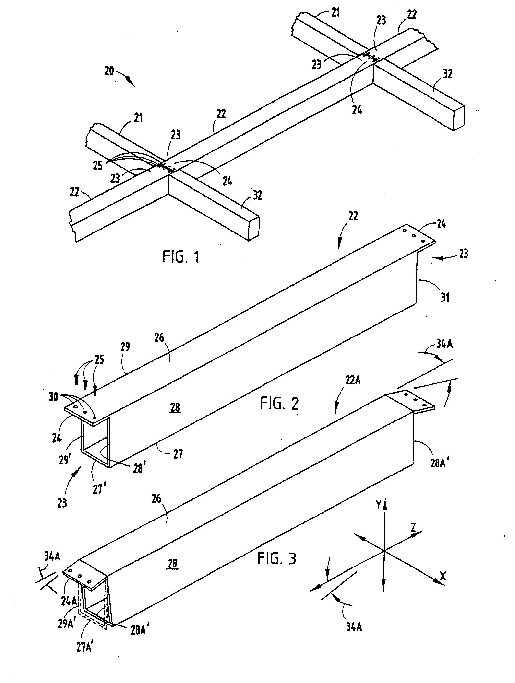
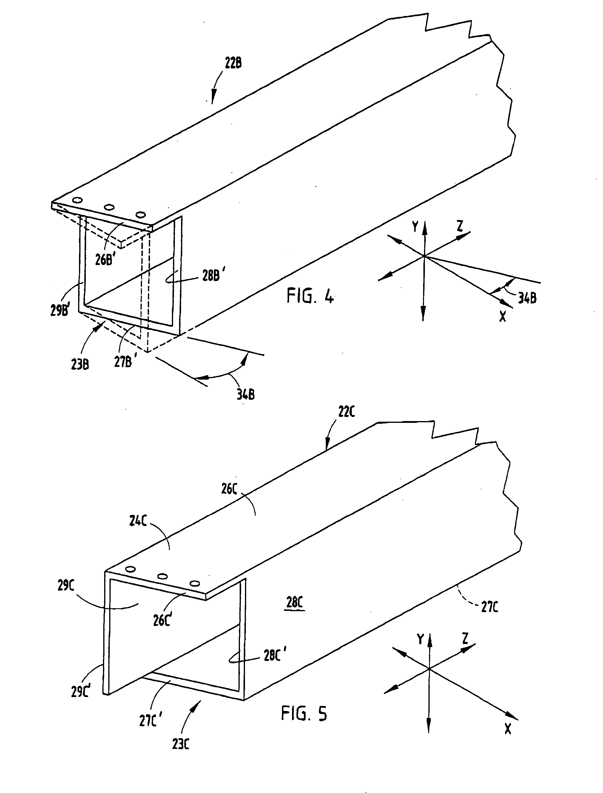
[0007] In another aspect of the present invention, a purlin includes a structural tube adapted to form a structural portion of a building. The structural tube has top, bottom, and opposing side walls. At least the top wall extends longitudinally to define an attachment tab. The bottom wall and at least one side wall has end surfaces defining a concavely-shaped recess adapted to fit closely against a beam with the attachment tab engaging a top of the beam. The attachment tab includes at least two apertures for receiving attachment bolts and has sufficient strength to both support the structural tube on the beam and also sufficient strength to retain the structural tube to the beam for stabilizing the beam.
[0014] The present structural purlin to beam connections described above are believed to be novel, useful, and unobvious, particularly in association with modern laser cutting technology, because the connecting configured ends are surprisingly and unexpectedly consistent and robust, and can be made in significant volumes with a reduced amount of high cost manual and skilled labor. Further, the cuts of the configured ends can be made at relatively high speed and quickly with low set-up time and cost.

Problems solved by technology

This takes substantial material, labor, and time, and further results in extra inventory as well as quality and dimensional control concerns.
While partial depth cuts can be made with saws, it is largely impractical to do so on a production basis for making building and roof beams and purlins, since partial depth cuts are manually intensive and time-consuming to set up, and further are difficult to accurately control in the heavy gauge metals and high-strength steels used in building beams.
Aside from the aforementioned problems, it is very difficult to exactly match the end point of a first cut with a second cut coming from another angle.
Notably, mis-cuts and poor dimensional control can be a significant problem when manufacturing structural beam components for buildings, since it can result in considerable field problems during construction and also may potentially raise safety concerns.
Still further, with traditional high-volume fabrication machinery, there is no easy way to cut at a varied non-linear direction through a tube.
In other words, most fabrication machinery is unsatisfactory for cutting configured ends of a structural tubular beam, when the configured end has multiple cut lines that are not in the same plane, and / or where the cuts are non-linear, and / or where the cut defines a cut direction where another wall interferes with positioning the cutting blade.
However, I have found that there is a lack of beam joint designs that take advantage of this technology.

Method used


Image

  • Building structure with purlin to beam connection
  • Building structure with purlin to beam connection
  • Building structure with purlin to beam connection

Examples


Embodiment Construction

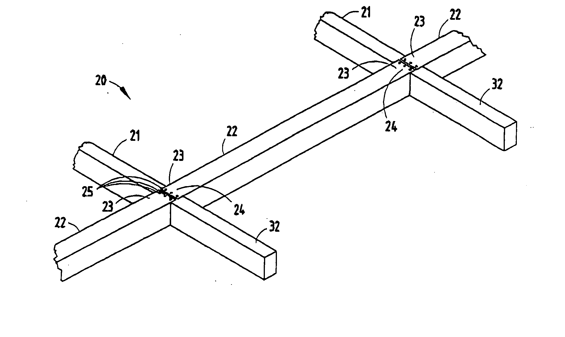
[0027] A metal frame 20 (FIG. 1) for a building structure includes one or more structural beams 21, and a plurality of tubular purlins 22 attached to the beams 21 to stabilize the beams 21 to form a rigid building structure, such as the illustrated roof frame structure. The tubular purlin 22 includes configured ends 23 forming a concave recess 23′ shaped to mateably engage a side of the beams 21 and further includes an attachment tab 24 extending longitudinally from the configured end 23 to a distance equal to about half of a width of the beam21. The configured end 23 and the attachment tab 24 both are integrally formed from material of the tubular purlin 22, as described below. The structural attachment tab 24 forms an arm that supports the configured end 23 on the structural beam 21 and structurally attaches the tubular purlin 22 to the structural beam 24 via a plurality of threaded screws 25 (three screws being illustrated).

[0028] The purlin 22 (FIG. 2) is a structural tube made...


PUM


Abstract

A metal frame for a building structure includes a structural beam, such as a truss, and a tubular purlin or trellis attached to the beam. The tubular purlin includes a configured end matably engaging a side of the beam and an attachment tab extending longitudinally from the configured end. The configured end and the attachment tab both are integrally formed from material of the tubular purlin. The structural attachment tab supports the configured end on the structural beam and structurally attaches the tubular purlin to the structural beam. In one form, the tubular purlin includes a wall section that covers an open end of the tubular beam. In another form, the configured end defines an angled recess setting the particular orientation of the beam relative to the purlin. In yet another form, interlock hooks are provided on the attachment tab.

Description

BACKGROUND [0001] The present invention relates to building structures having structural beams and purlins connected between the beams to create a frame, and also relates to building structures having both purlins and trellis. [0002] Tubular purlins are for the most part presently connected to main beams (e.g. trusses) with welded end plates that cover the end of the tubular purlins. The end plates are bent at the top and have an extending flange with holes for receiving bolts to secure the purlins to a main beam or truss. For example, see Porter U.S. Pat. No. 4,275,534. The end plates are pre-formed separate from the tubular purlins and then attached by welding. This takes substantial material, labor, and time, and further results in extra inventory as well as quality and dimensional control concerns. An improvement is desired to reduce the amount of raw material required for manufacture of building structures, to reduce the number of inventoried components, to simplify the manufac...

Claims


Application Information

Patent Timeline
IPC IPC(8): E04B1/00E04B1/24E04B7/02E04D12/00E04H12/00
CPCE04B1/24E04B7/024E04B7/028E04B2001/0092E04D12/004E04B2001/2451E04B2001/2454E04B2001/2457E04B2001/249E04B2001/2409
Inventor PORTER, WILLIAM H.
Owner PORTER WILLIAM H
Learn More