Docking assistant

a technology for assistants and doctors, applied in the field of doctor assistants, can solve problems such as not always possibl

Active Publication Date: 2005-12-22
CHEMTRON RES
View PDF29 Cites 18 Cited by
  • Summary
  • Abstract
  • Description
  • Claims
  • Application Information

AI Technical Summary

Benefits of technology

[0003] Many day-to-day driving situations require that an operator of a motor vehicle guide the motor vehicle along a specific course and bring the vehicle to a stop at a specific location, for example in a parking bay or at a loading platform. To assist a vehicle operator in such situations, the Japanese Patent Application JP 2001-343212 A describes a camera-based system for the guided entry into a parking bay whose boundaries are marked on the road surface. The system utilizes the fact that parking bays marked on the road surface are typically bounded on the right and left by clearly visible lines (lane marking signatures). In the image data acquired by the camera integrated in the vehicle, these visual signatures (boundary lines) are identified within an image-processing unit, and their orientation is measured. Since the visual signatures are parallel straight lines, they are also reproduced as straight lines in the camera image data, so that their angular deviation from the x- and y-axis of the camera image can easily be determined. From the angular deviations of both straight-line sections relative to each other and the knowledge of the distance that separates them, the vehicle's distance to the parking bay and its orientation relative to the same can be calculated in a geometrically simple manner. The image data are presented to the driver of the vehicle on a display, directional arrows being superposed on the display to indicate how far and in which direction the vehicle needs to be controlled in order to reach the parking bay.
[0005] A camera-based position detection and lane control system for motor vehicles that is rugged with respect to obscuration and soiling of the visual signatures, is described in the post-published German Patent Application DE 10323915.4. It discusses determining the position of the motor vehicle relative to a visual signature, which is used to mark the destination, by matching a template to camera image data acquired from the motor vehicle's surrounding field. This requires superposing the visual signature in the field surrounding the vehicle on a template of a visual signature stored in a memory. When the existing coordinate systems are known, the position of the motor vehicle relative to the visual signature can be directly inferred, in particular, from the compression and rotation parameters of this template matching. By using template matching for the problem at hand, one very advantageously utilizes the fact that this method is highly reliable, even when the visual signature in the image data is not fully visible due to obscuration or soiling. As do the other known related art methods for assisting the driver of a motor vehicle in approaching a destination, the system described in the German Patent Application DE 10323915.4 also requires that the destination be provided with a specific, previously known signature. In order for the visual signature to be uniquely identifiable in the image data, it must be conceived in a way that makes it clearly distinguishable from other visual signatures actually existing in the surrounding vicinity or from those that are only seemingly present. SUMMARY OF THE INVENTION
[0006] An object of the present invention is to provide a method for assisting vehicle guidance on the basis of image data, particularly when maneuvering trucks toward docking stations, as well as to provide a device suited for implementing the method, which functions without the need for affixing specific visual signatures at the destination.
[0010] In this manner, a driver assistance is able to be devised by using the device according to the present invention and on the basis of the method according to the present invention, which computes a trajectory describing an optimized travel path to at least the most proximate destination, based solely on the knowledge of the geometric appearance of the destination, without having to affix specific symbols or markings.

Problems solved by technology

In reality, however, this is not always possible, due to soiling of and wear to the lane markings.

Method used


Image

  • Docking assistant
  • Docking assistant
  • Docking assistant

Examples


Embodiment Construction

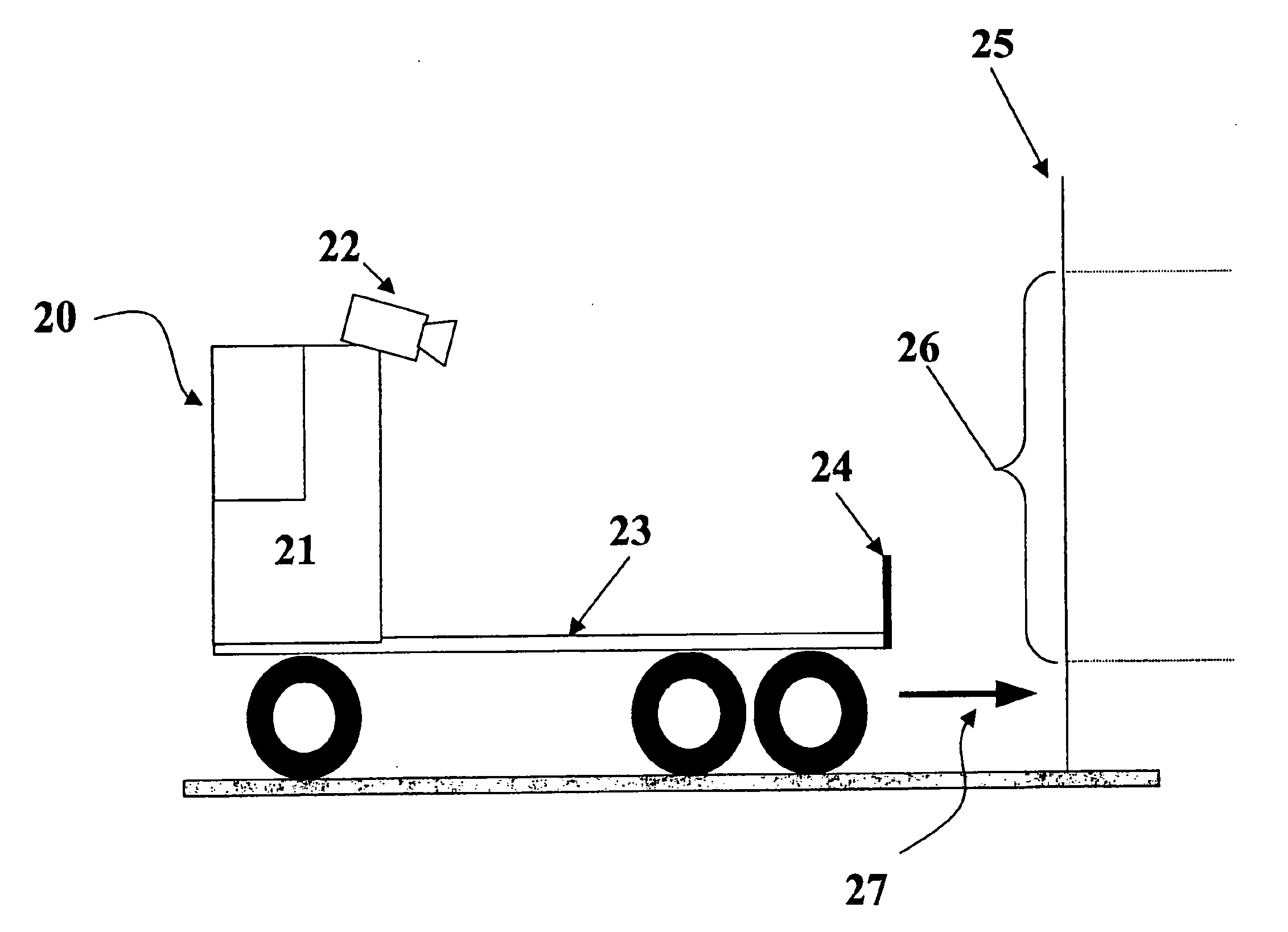
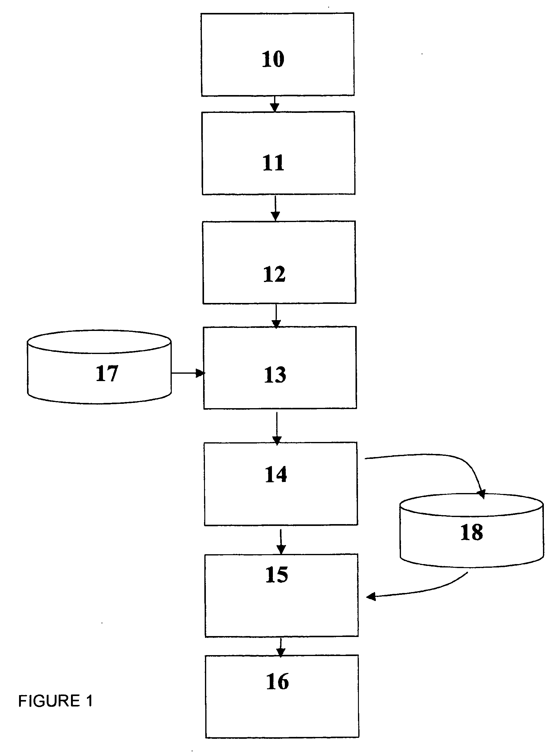
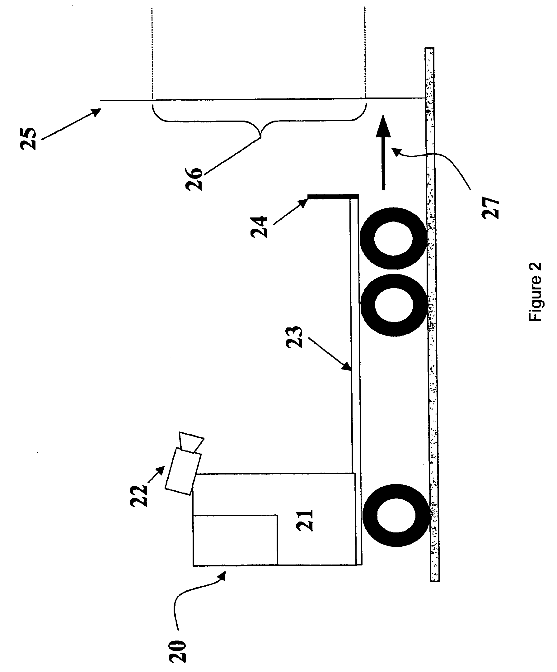
[0015] As becomes clear from FIG. 1, the method according to the present invention is essentially sequential, in a first step, an image sensor (10) recording image data from the field surrounding a motor vehicle. In this connection, it is generally a question of a camera sensor which records image data in the visible light spectrum. However, it is equally [0016] conceivable that the image sensor (20) functions within an essentially invisible wavelength range, in particular in the infrared or in the ultraviolet wavelength range. Using such an image sensor makes it advantageously possible for the field surrounding the motor vehicle to be recorded to be actively illuminated by headlights which radiate light in this wavelength range, while objects or people in the area are exposed to a nonglare-type illumination. On the other hand, within the scope of the present invention, a millimeter wave radar or a lidar may be used as image sensor (10).

[0017] The image data generated by image sens...


PUM


Abstract

Many day-to-day driving situations require that an operator of a motor vehicle guide the motor vehicle along a specific course and bring the vehicle to a stop at a specific location, for example in a parking bay or at a loading platform. To assist a vehicle operator in such situations, a method and a suitable device for implementing this method, include detecting the potential target objects in the image data of an image sensor and identifying the potential target objects as potential destinations in a multi-stage exclusionary method, whereupon a trajectory describing an optimized travel path is computed at least in relation to the most proximate destination. By using the multi-stage exclusionary method according to the present invention, it is possible to reliably identify potential destinations in complex image scenarios solely on the basis of their geometric form, even when the destinations have not been encoded by specific symbols.

Description

[0001] Priority is claimed to German Patent Application No. DE 10 2004 028 763.5, filed on Jun. 16, 2004, the entire disclosure of which is incorporated by reference herein. [0002] The present invention is directed to a method for assisting vehicle guidance on the basis of image data, particularly when maneuvering trucks toward docking stations, as well as to a device suited for implementing the method. [0003] Many day-to-day driving situations require that an operator of a motor vehicle guide the motor vehicle along a specific course and bring the vehicle to a stop at a specific location, for example in a parking bay or at a loading platform. To assist a vehicle operator in such situations, the Japanese Patent Application JP 2001-343212 A describes a camera-based system for the guided entry into a parking bay whose boundaries are marked on the road surface. The system utilizes the fact that parking bays marked on the road surface are typically bounded on the right and left by clear...

Claims


Application Information

Patent Timeline
IPC IPC(8): B60R1/00B60R21/00B62D6/00G01B11/00G01B11/26G05D1/02G06K9/00G06K9/32G08G1/0969G08G1/123
CPCG06K9/3241G06V10/255G05D1/0246
Inventor GEHRING, OTTMARHEILMANN, HARROHOLZMANN, FREDERICSCHWARZHAUPT, ANDREASSPIEGELBERG, GERNOTSULZMANN, ARMIN
Owner CHEMTRON RES
Why Eureka
Try Eureka