Charge pump of a phase locked loop with switchable system bandwidth and method for controlling such a charge pump

Inactive Publication Date: 2005-12-22
ATMEL GERMANY
View PDF6 Cites 5 Cited by
  • Summary
  • Abstract
  • Description
  • Claims
  • Application Information

AI Technical Summary

Benefits of technology

[0013] It is therefore an object of the present invention to provide a charge pump for a phase locked loop and a method for controlling a charge pump, making possible rapid settling of the phase locked loop at a frequency change through both high current levels and thus wide loop bandwidth, and through small differences in the phase offset when changing between low and high current levels of the charge pump, in order to be able to switch the bandwidth of the phase locked loop without an additional control action. In addition, a dead time for very low current levels of the charge pump is to be avoided.

Problems solved by technology

In addition to the various static phase errors dealt with in U.S. Pat. No. 6,011,822 for different control voltages of the VCO, however, phase errors that vary with current level also arise in phase locked loops having switchable bandwidths that are controlled through the charge current of the charge pump.
Since the loop bandwidth in this case is very wide, the noise present in the loop modulates the output frequency of the VCO, which is not desired.
In real charge pumps, however, leakage currents, asymmetries and production variations in the components used result in a phase offset between the signal of the reference frequency source and the signal of the 1 / N divider.
This offset is settled out with the narrow bandwidth of the phase locked loop, which takes a relatively long time.
On the other hand, the loop bandwidth is increased by the high current level in the charge pump, and thus a large amount of noise is modulated onto the VCO.

Method used


Image

  • Charge pump of a phase locked loop with switchable system bandwidth and method for controlling such a charge pump
  • Charge pump of a phase locked loop with switchable system bandwidth and method for controlling such a charge pump
  • Charge pump of a phase locked loop with switchable system bandwidth and method for controlling such a charge pump

Examples


Embodiment Construction

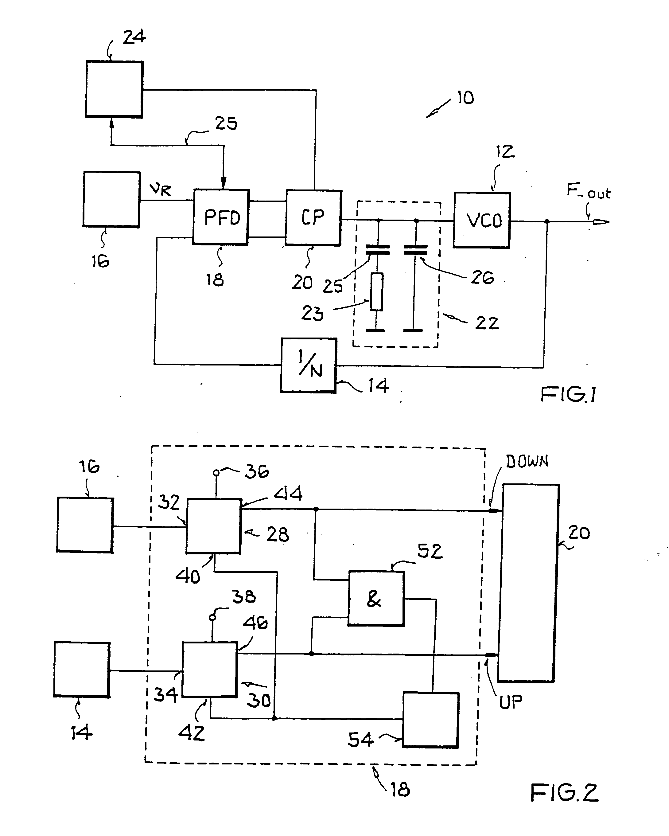
[0050]FIG. 1 shows a phase locked loop 10 having a VCO 12, a frequency divider 14, a reference frequency source 16, a phase / frequency detector PFD 18, a charge pump 20 (charge pump CP), a loop filter 22 and a control unit 24. The VCO 12 contains, for example, an LC resonant circuit with an inductance L and a capacitance C, the value of which is a function of a DC control voltage. Inductance and controllable capacitance determine the oscillation frequency and thus the frequency F_out of the VCO. The VCO frequency divided down by the 1 / N divider 14 is fed to the phase / frequency detector 18 together with a reference frequency output by the reference frequency source 16. The phase / frequency detector uses “UP” and “DOWN” pulses to control the charge pump 20, which supplies the loop filter 22 with corresponding charge current pulses and discharge current pulses. The loop filter 22 has at least one capacitive element 25, 26, whose total charge Q is determined by the charge and discharge cu...


PUM


Abstract

A charge pump of a phase locked loop and method thereof, includes a first current source that supplies a first additive partial current to a node, a first current sink that draws a first subtractive partial current from the node, a second current source that supplies a second additive partial current to a node, and a second current sink that draws a second subtractive partial current from the node, wherein a sum of the currents (I—2+, I—1−) provides a charge current for a loop filter of the phase locked loop and a sum of the currents (I—1+, I—2−) provides a discharge current for the loop filter. The charge pump also includes a first current control element and a second current control element. The first current control element controls the sum of the first additive partial current (I—1+) and the second subtractive partial current (I—2−), and the second current control element controls the sum of the first subtractive partial current (I—1−) and the second additive partial current (I—2+).

Description

[0001] This nonprovisional application claims priority under 35 U.S.C. § 119(a) on German Patent Application No. 102004031913.8, which was filed in Germany on Jun. 21, 2004, and which is herein incorporated by reference. BACKGROUND OF THE INVENTION [0002] 1. Field of the Invention [0003] The present invention relates to a charge pump of a phase locked loop, having a first current source that supplies a first additive partial current to a node, and having a first current sink that draws a first subtractive partial current from the node, having a second current source that supplies a second additive partial current to a node, and having a second current sink that draws a second subtractive partial current from the node. The invention further relates to a method for controlling the charge pump of the phase locked loop. [0004] 2. Description of the Background Art [0005] A charge pump of this nature, which is also known as a “differential charge pump,” and a method of this nature, are kn...

Claims


Application Information

Patent Timeline
IPC IPC(8): H03L7/00H03L7/08H03L7/089H03L7/107
CPCH03L7/107H03L7/0898H03L7/1072
Inventor HANSELMANN, ANDREAS
Owner ATMEL GERMANY
Why Eureka
Try Eureka