
Landing assist apparatus with releasable slip ring

a technology of landing assist and slip ring, which is applied in the direction of alighting gear, transportation and packaging, skis/runners, etc., can solve the problems of specifically designed helicopters lacking other desirable features, art aircraft/ship landing assist systems, etc., and achieve the effect of avoiding potentially catastrophic damage to the helicopter

Inactive Publication Date: 2005-12-22
THE BOEING CO
View PDF2 Cites 10 Cited by
  • Summary
  • Abstract
  • Description
  • Claims
  • Application Information

AI Technical Summary

Benefits of technology

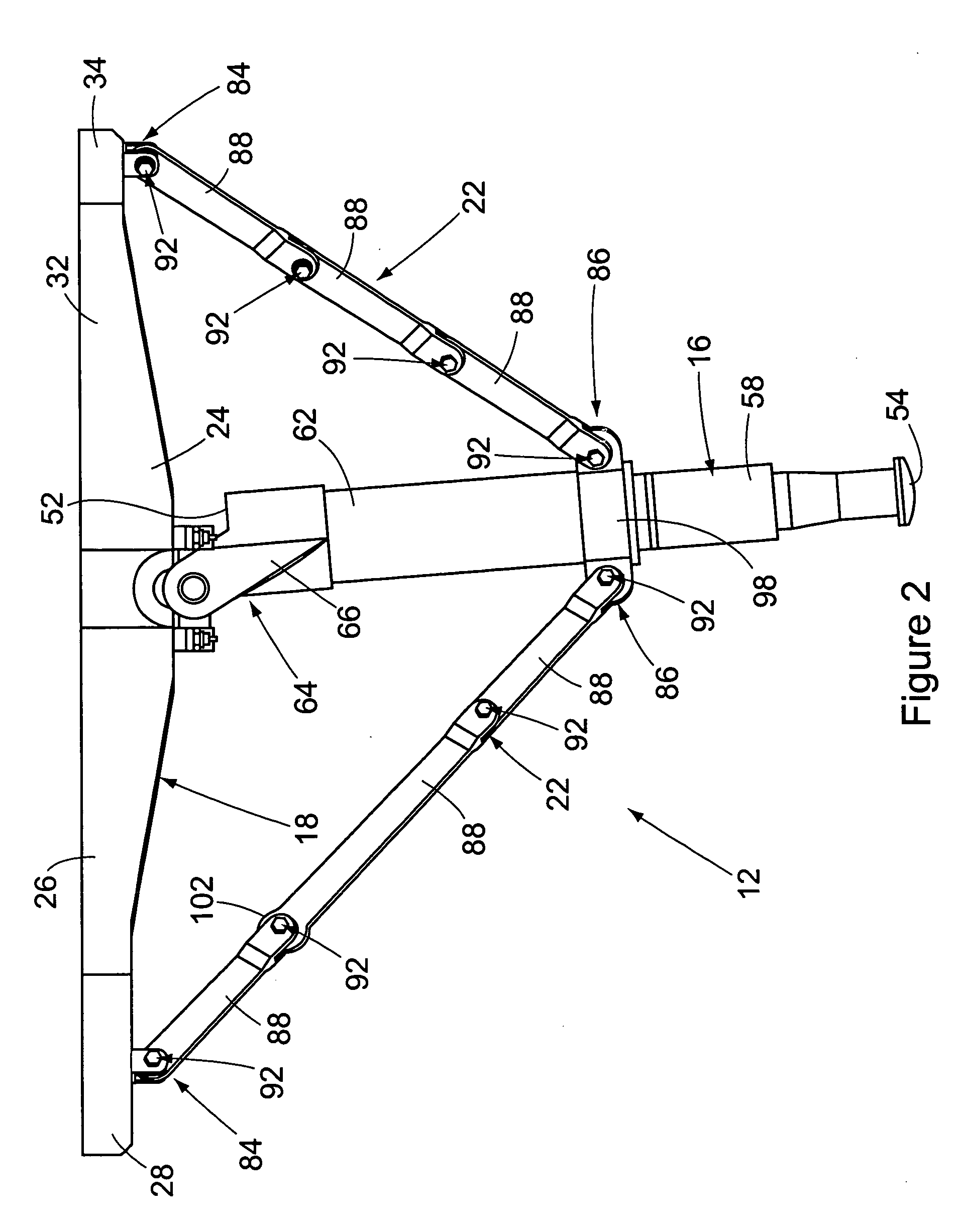
The present invention provides an aircraft landing assist apparatus that can be retrofit to existing aircraft that have not been designed for shipboard landings. The apparatus is designed to be easily installed and remove, with the ability to collapse in a controlled manner to prevent damage to the aircraft and injury to the pilot and copilot. The apparatus includes a landing probe that is secured to the aircraft and stabilizing struts that hold the probe in place. The struts are designed to collapse when a compressive force is exerted on the probe, preventing any damage or injury. The apparatus is supported from the same internal structure of the aircraft that receives the loads when flying. The invention solves the problem of rough landings and provides a safer way to land on a ship.

Problems solved by technology

The prior art aircraft / ship landing assist systems are therefore disadvantaged in that the systems are limited to use with helicopters that are dedicated for use with the landing assist system.
These specifically designed helicopters may be lacking in other desirable features for helicopters, for example the various different types of weaponry available on modern day military aircraft.

Method used


Image

  • Landing assist apparatus with releasable slip ring
  • Landing assist apparatus with releasable slip ring
  • Landing assist apparatus with releasable slip ring

Examples


Embodiment Construction

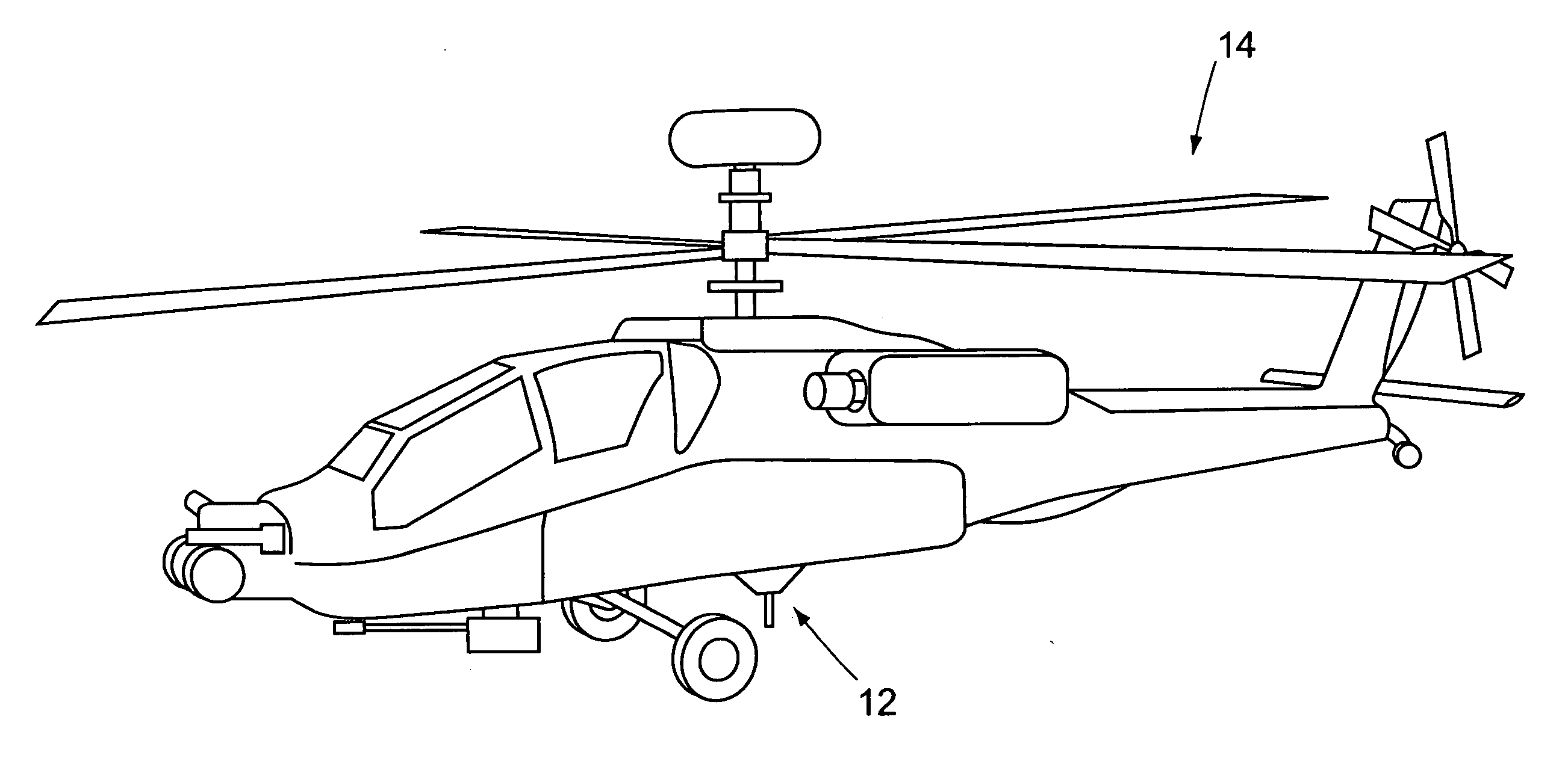
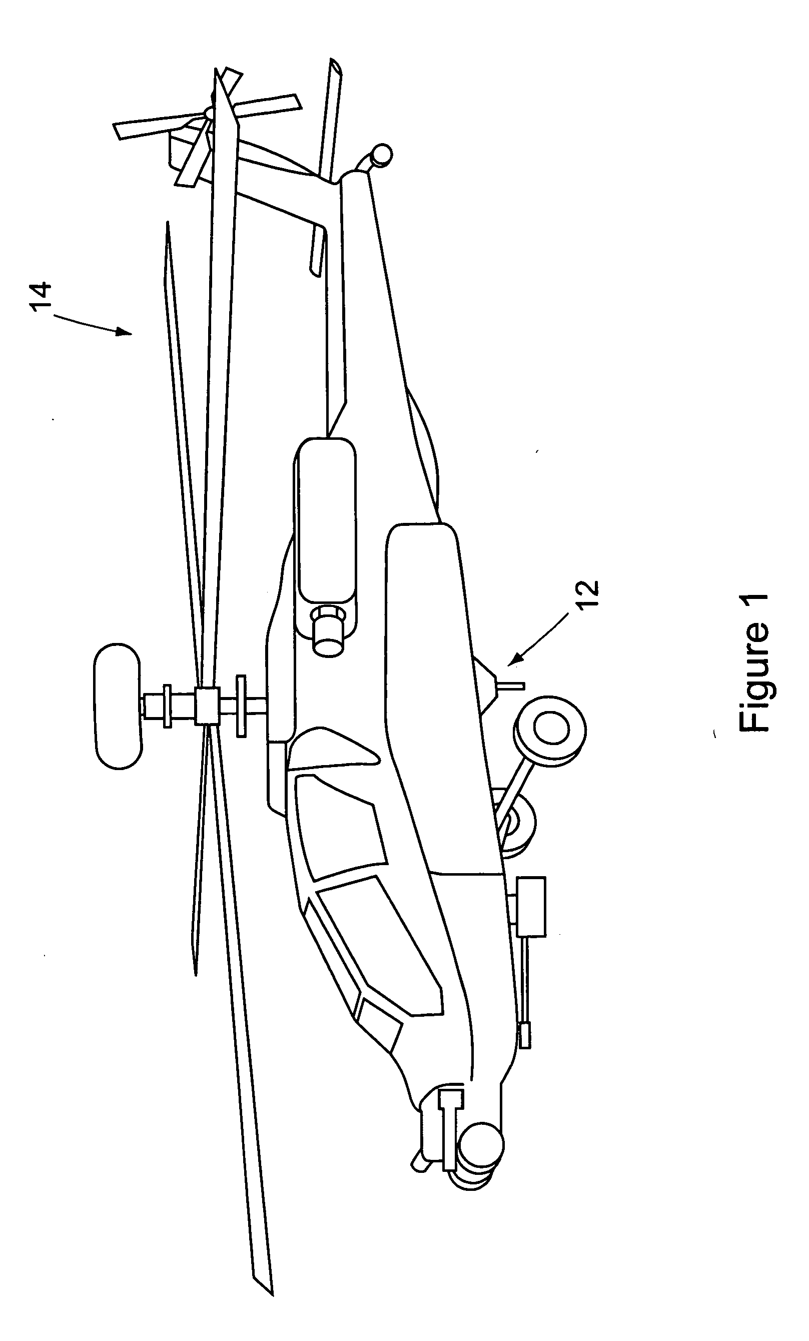
[0056]FIG. 1 shows the aircraft landing assist apparatus 12 of the invention employed on an aircraft 14. Specifically, FIG. 1 shows the apparatus 12 installed on the underside of a helicopter-type aircraft, for example an AH64 Apache helicopter. It should be understood that the particular type of aircraft 14 with which the apparatus 12 is shown in FIG. 1 is illustrative only. It is not intended that the apparatus 12 be limited to use with any one particular type of aircraft.

[0057] The apparatus 12 is specifically designed to be retrofit to existing helicopters that have not previously been designed for shipboard landings. In addition, on rough landing of the aircraft using the apparatus 12, the apparatus is designed to collapse in a controlled manner beneath the aircraft 14, thereby avoiding any damage to internal components of the aircraft such as an ammunition container and / or a fuel storage cell. Although the preferred embodiment of the apparatus is retrofit to an existing aircr...


PUM


Abstract

An aircraft landing assist apparatus is designed to be retrofit to existing aircraft having internal constructions that have been modified to support the apparatus. The apparatus is designed so that on rough landings of the aircraft on a ship deck, the apparatus will collapse in a controlled manner to avoid any damage to ammunition and / or fuel storage areas of the aircraft.

Description

[0001] This invention was developed in the course of work under U.S. Government Army Contract DAAH23-99-C-0111. The U.S. government may possess certain rights in the invention.BACKGROUND OF THE INVENTION [0002] (1) Field of the Invention [0003] The present invention pertains to an aircraft landing assist system. More specifically, the present invention pertains to a mounting system for an aircraft landing assist probe, and a method of retrofitting an aircraft with the mounting system to adapt that aircraft for landing on a deck of a ship. [0004] (2) Description of the Related Art [0005] Landing assist systems have been developed that facilitate the landing of an aircraft, for example, a helicopter, on the deck of a ship. An example of one such system is the aircraft / ship integrated secure and traverse (ASIST) deck landing system developed by Indal Technologies, Inc. of Ontario, Canada. [0006] In a typical aircraft landing assist apparatus employed in landing a helicopter on the deck...

Claims


Application Information

Patent Timeline
Patent Type & Authority Applications(United States)
IPC IPC(8): B64C25/00
CPCB64C2025/325B64C25/00
Inventor TEBON, DARRIN
Owner THE BOEING CO
Learn More