
Method and apparatus for configuring and testing a machine vision detector

a machine vision and detector technology, applied in the field of automatic detection and inspection of objects, can solve the problem of not being able to display all captured images, and achieve the effect of avoiding excessive tim

Active Publication Date: 2005-12-15
COGNEX TECH & INVESTMENT
View PDF99 Cites 35 Cited by
  • Summary
  • Abstract
  • Description
  • Claims
  • Application Information

AI Technical Summary

Benefits of technology

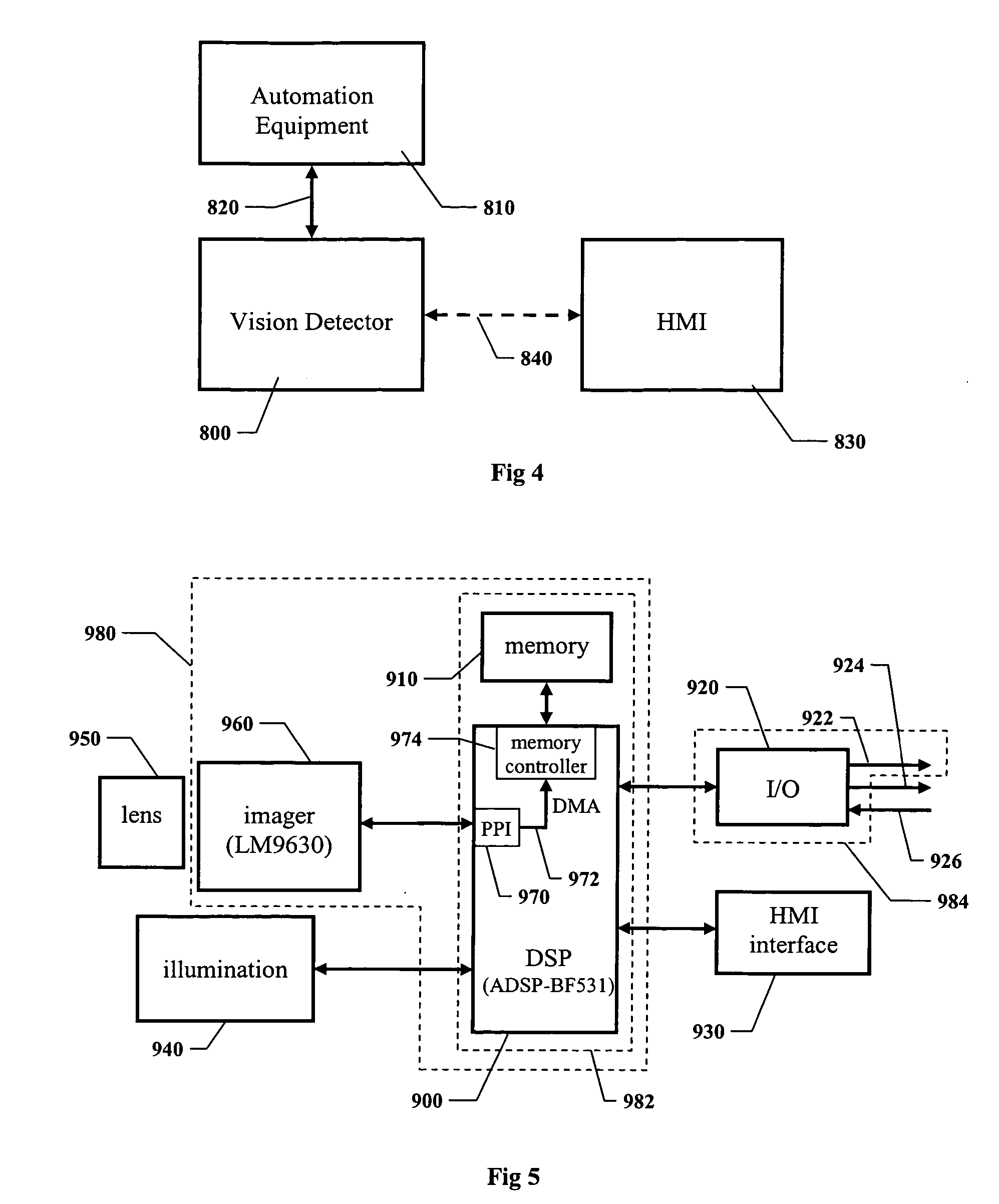
[0050] In a further modification to this exemplary embodiment, the captured sequence of images are stored in a memory on the vision detector, and the GUI is running on a separate human-machine interface (HMI) connected to the vision detector by means of a communications interface. To avoid excessive time that might be needed to transmit the entire captured sequence of images to the HMI, the vision detector creates and transmits the low-resolution thumbnail images for display in the filmstrip window. Only at such times as a new full-resolution image is needed by the HMI for display in the image view window is the appropriate full-resolution image transmitted.
[0051] In another exemplary embodiment, a configuration of the vision detector can be improved using additional images in the captured sequence of images. Note that there is no requirement or expectation that only one training image be used to configure a vision detector. It is desirable to confirm reasonable operation of the vision detector for a variety of viewing perspectives of a variety of objects, and to adjust the configuration as necessary to achieve that.
[0064] In a further modification to this exemplary embodiment, the GUI is running on a separate HMI connected to the vision detector by means of a communications interface. To avoid excessive time that might be needed to transmit all of the stored images to the HMI, the vision detector creates and transmits the low-resolution thumbnail images for display in the filmstrip window. Only at such times as when a new full-resolution image is needed by the HMI for display in the image view window is the appropriate full-resolution image transmitted.

Problems solved by technology

Typically it is not practical to display all of the captured images at once at a display resolution sufficient for the user to see useful detail in each image, so instead a portion of the sequence is displayed at one time.

Method used


Image

  • Method and apparatus for configuring and testing a machine vision detector
  • Method and apparatus for configuring and testing a machine vision detector
  • Method and apparatus for configuring and testing a machine vision detector

Examples


Embodiment Construction

Basic Operation of the Vision Detector Method and Apparatus

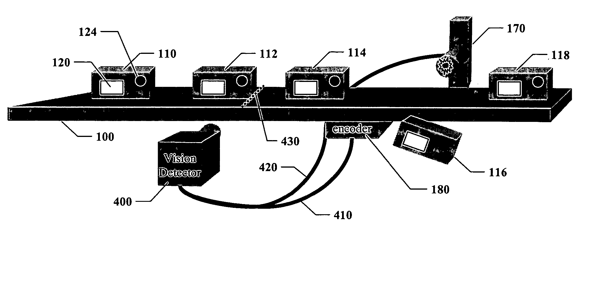
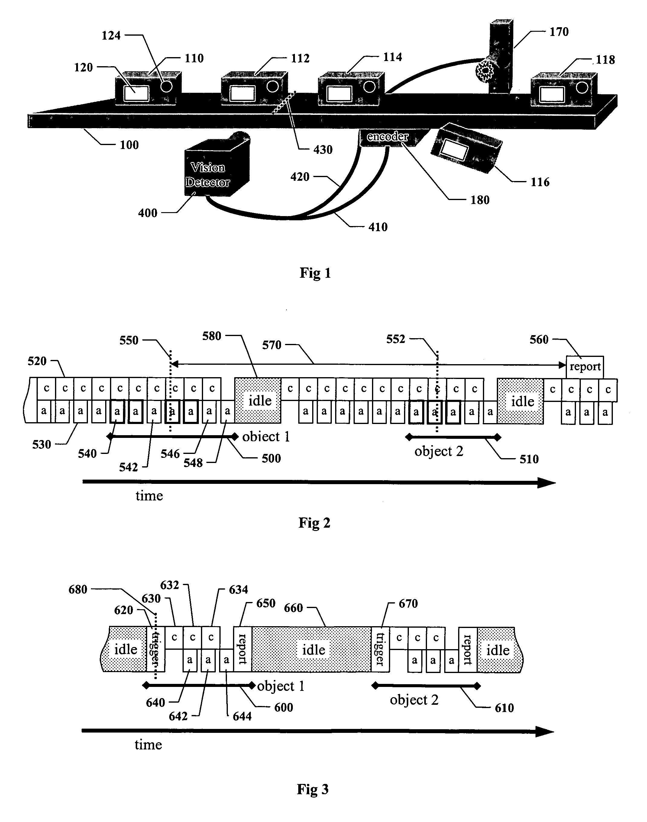
[0081]FIG. 1 shows an illustrative embodiment of a vision detector according to the Vision Detector Method and Apparatus, inspecting objects on a production line. A conveyer 100 transports objects to cause relative movement between the objects and the field of view of vision detector 400. Objects 110, 112, 114, 116, and 118 move left to right on a conveyer 100. Each object is expected to contain certain features, for example a label 120 and a hole 124. Objects incorrectly manufactured may be missing one or more features, or may have unintended features; for example, object 116 is missing the hole. On many production lines motion of the conveyer is tracked by a shaft encoder 180. A vision detector 400 detects the presence of an object by visual appearance and inspects it based on appropriate inspection criteria. If an object is defective, the vision detector sends signal 420 to reject actuator 170 to remove the object from ...


PUM

PropertyMeasurementUnit
threshold taaaaaaaaaa
field of viewaaaaaaaaaa
decision thresholdaaaaaaaaaa

Abstract

Disclosed are systems and methods for configuring a vision detector, wherein a training image is obtained from a production line operating in continuous motion so as to provide conditions substantially identical to those that will apply during actual manufacturing and inspection of objects. A training image can be obtained without any need for a trigger signal, whether or not the vision detector might use such a signal for inspecting the objects. Further disclosed are systems and methods for testing a vision detector by selecting, storing, and displaying a limited number of images from a production run, where those images correspond to objects likely to represent incorrect decisions.

Description

RELATED APPLICATION [0001] This application is a continuation-in-part of co-pending U.S. patent application Ser. No. 10 / 865,155, entitled METHOD AND APPARATUS FOR VISUAL DETECTION AND INSPECTION OF OBJECTS, by William M. Silver, filed Jun. 9, 2004, the teachings of which are expressly incorporated herein by reference, and referred to herein as the “Vision Detector Method and Apparatus”.BACKGROUND OF THE INVENTION [0002] 1. Field of the Invention [0003] The invention relates to automated detection and inspection of objects being manufactured on a production line, and more particularly to the related fields of industrial machine vision and automated image analysis. [0004] 2. Description of the Related Art [0005] Industrial manufacturing relies on automatic inspection of objects being manufactured. One form of automatic inspection that has been in common use for decades is based on optoelectronic technologies that use electromagnetic energy, usually infrared or visible light, photoelec...

Claims


Application Information

Patent Timeline
Patent Type & Authority Applications(United States)
IPC IPC(8): G01N21/00G06F3/00H04N13/02
CPCG06T7/0004G06F3/04817G06F3/0485G06V20/00G06T7/00G01N21/00
Inventor EAMES, ANDREWMIRTICH, BRIAN V.SILVER, WILLIAM M.
Owner COGNEX TECH & INVESTMENT
Learn More