
Power converter

a power converter and converter technology, applied in the direction of dc-ac conversion without reversal, mechanical energy handling, transmission systems, etc., can solve the problem of limited number of additional dc/dc converters, achieve low harmonic, simplify gate drives, and smooth current and voltage delivery

Active Publication Date: 2005-12-15
SMA SOLAR TECH AG
View PDF2 Cites 263 Cited by
  • Summary
  • Abstract
  • Description
  • Claims
  • Application Information

AI Technical Summary

Benefits of technology

[0004] A first object of the invention is to enable independent control in each of the modules used in the system, hereby providing an easy form of controlling power switches used inside a power converter.

Problems solved by technology

Due to this centralised control structure, the number of additional DC / DC converters is limited as is the possibility of simultaneously using DC / DC converters for different types of green power.

Method used


Image

  • Power converter
  • Power converter
  • Power converter

Examples


Embodiment Construction

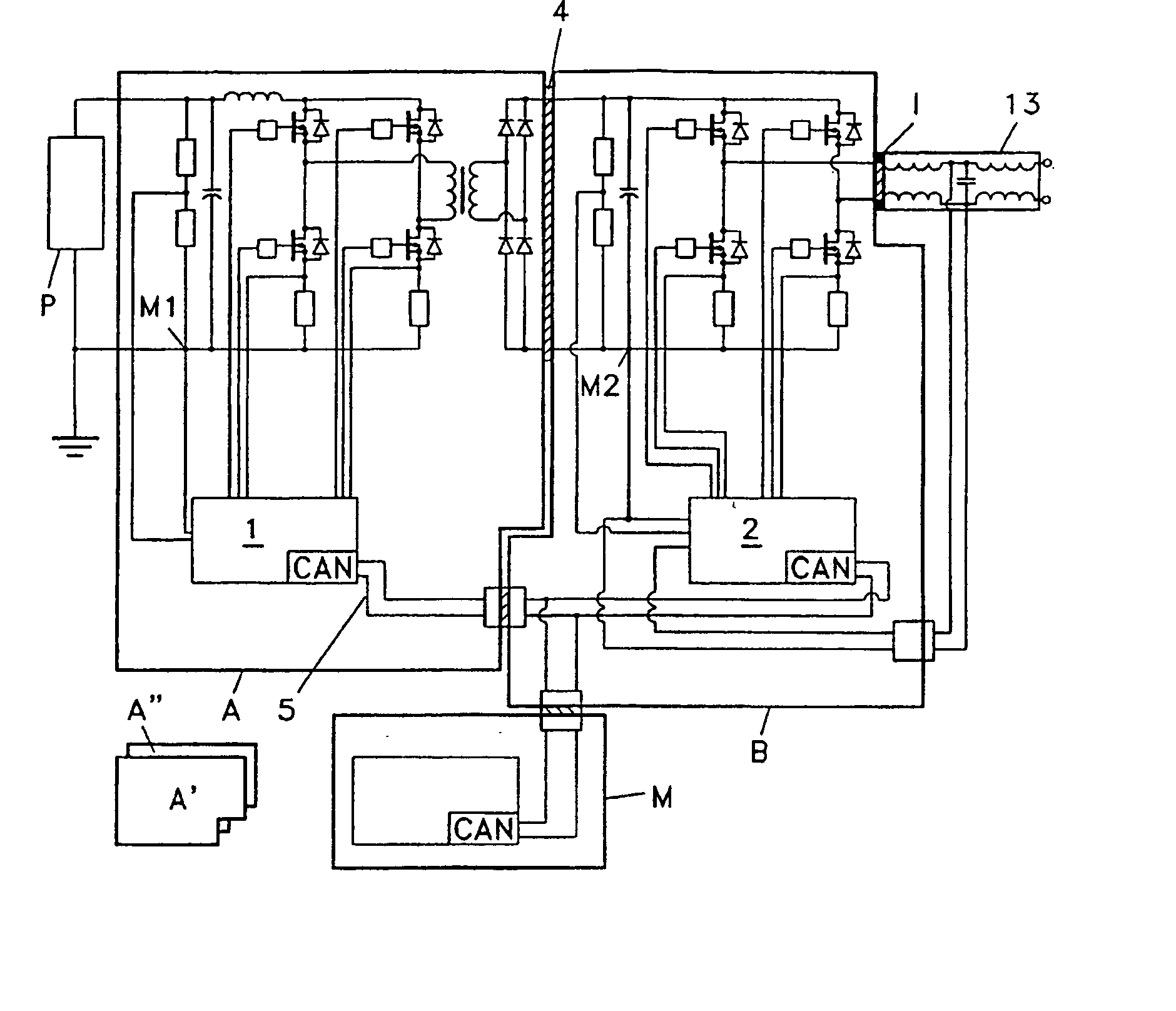
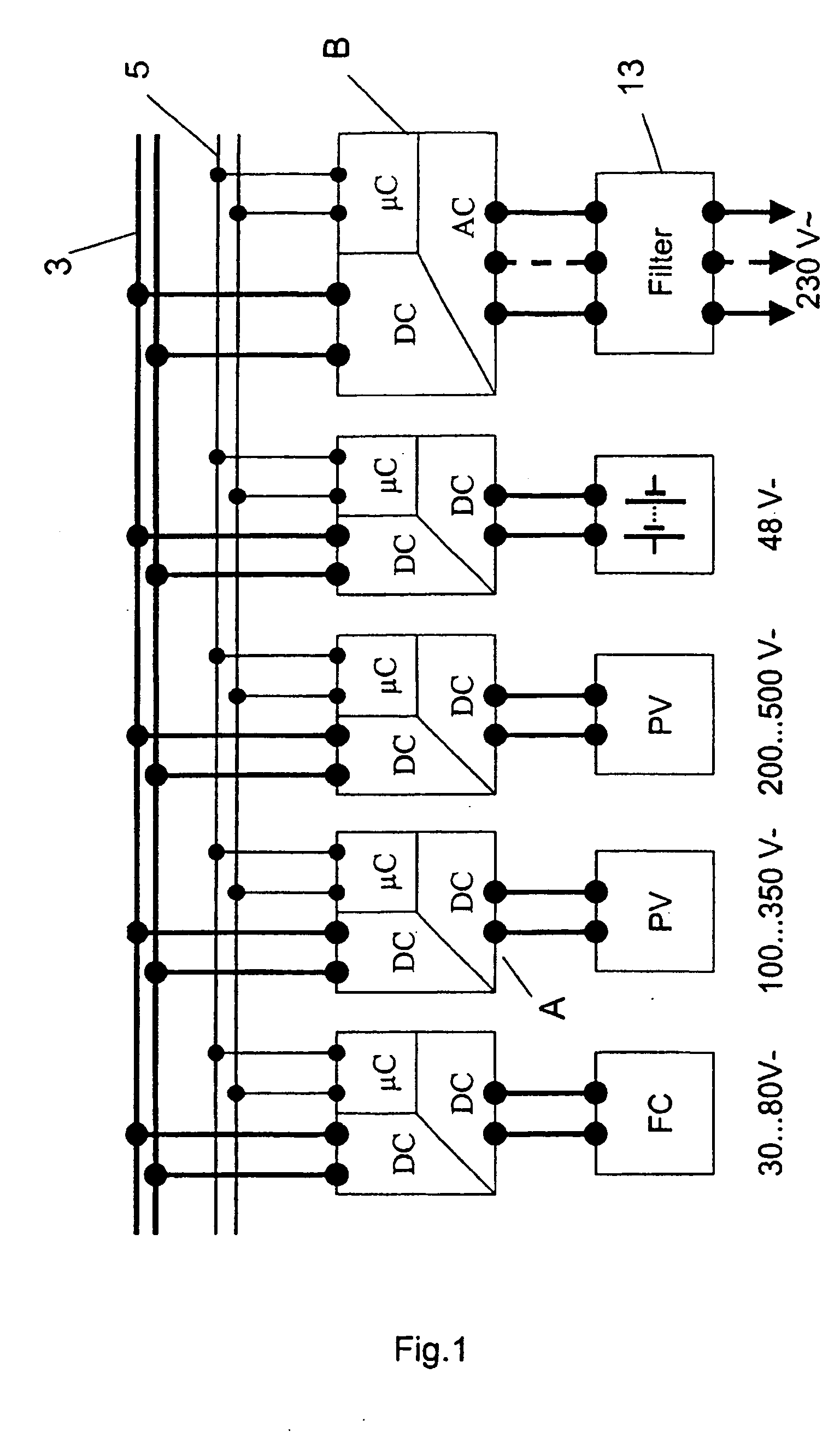
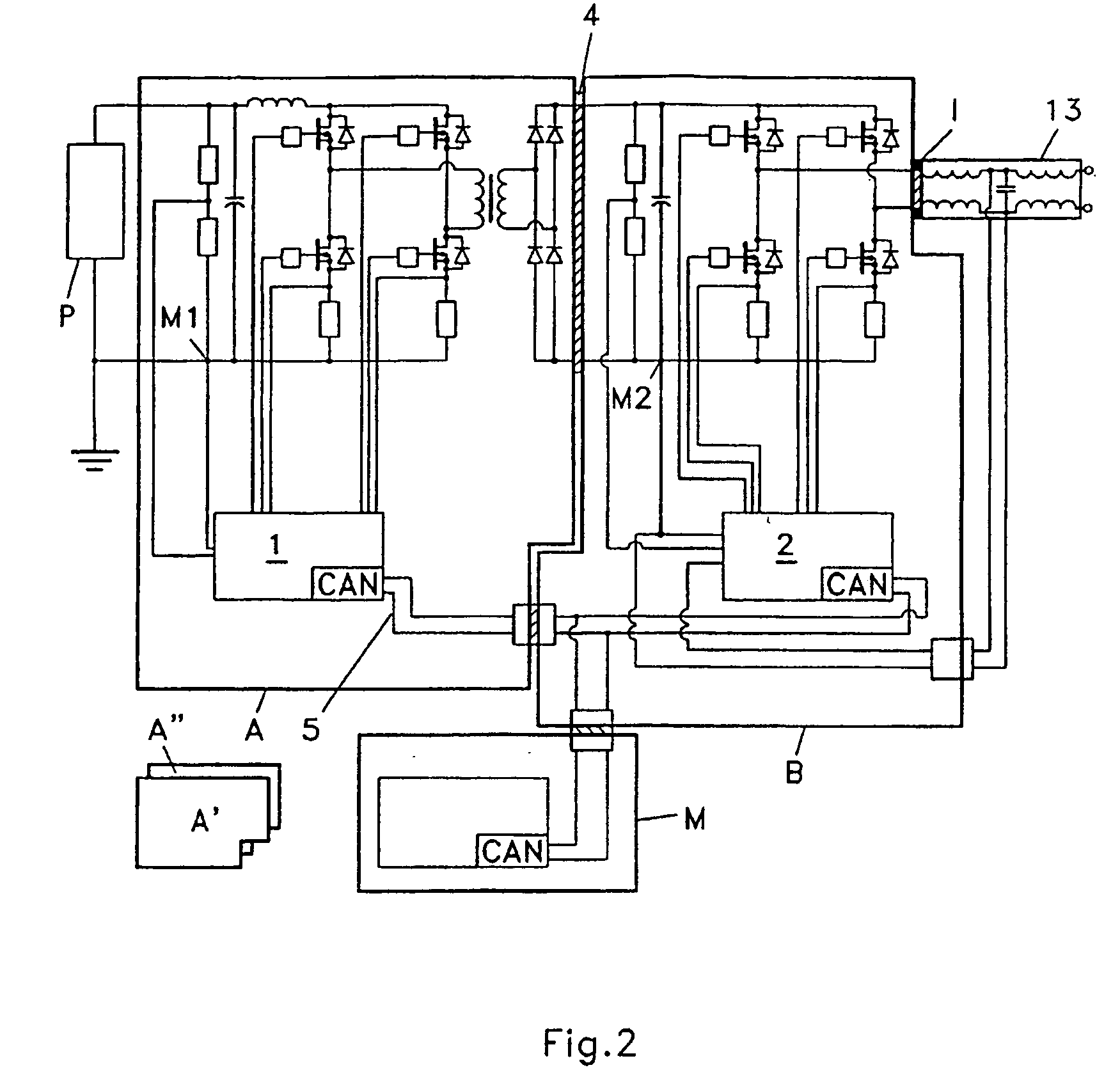
[0043]FIG. 1 shows how a DC / DC-module A is connected to a DC-bus 3, which is common to several other DC / DC-converters. They are all feeding energy into the DC-bus, and DC / AC-inverter B taps the DC-bus and converts the energy into a grid voltage and grid frequency. A filter 13 as described later in this application may be used. Such filter is also a module, as shown in FIG. 2. The modules A and B are connected to each other via an interface 4 shown on FIG. 2. Such interface is preferably an easy insertion interface. The modules communicate via a serial bus 5. The CAN bus is preferred. The control of the system consisting of modules A and B is divided into two control circuits 1 and 2 galvanically isolated from each other. In this embodiment, a micro controller regulates the DC / DC-converter, and a Digital Signal Processor regulates the DC / AC-inverter. The DC / DC-converter and controller are placed on a first module A and AC / DC-inverter and controller are placed on a second module B. In...


PUM


Abstract

A power converter for converting energy from a green power unit as e.g. a solar cell into energy fed into the commercial grid is described. The object is to provide a versatile modularized power converter with eased access to control of the power switches. Another object is to improve the electrical efficiency. This is achieved by using an independent controller on a DC / DC module and an independent controller on a DC / AC module, whereby the the two independent controllers communicate with each other and the outside world by means of a communication bus. Further, the DC / DC module of the power converter comprises a transformer which transfers energy from the DC / DC module to the DC / AC module. This design enables independent control of the modules and eases controllability of the power switches in order to suppress retroaction from pulsations generated on the mains when supplying energy to a single phase grid. Hereby the electrical efficiency of the power converter is increased. Also, an active snubber circuit is described which further increase the efficiency.

Description

CROSS REFERENCE TO RELATED APPLICATIONS [0001] This application is entitled to the benefit of and incorporates by reference essential subject matter disclosed in international Patent Application No. PCT / DK2003 / 000422 filed on Jun. 20, 2003 and Danish Patent Application No. PA 2002 00966 filed on Jun. 23, 2002.FIELD OF THE INVENTION [0002] The invention concerns a power converter for use in green power applications, and concerns particularly a module concept. “Green power” is the term used for energy sources like wind, sun or fuel cells, and the inventive power converter can be used for these different sources of electrical energy. BACKGROUND OF THE INVENTION [0003] The power generated by green power units is converted into a voltage and a frequency suited to the commercial mains. Conversion is typically done by using a switch mode DC / DC-converter followed by a conversion into AC. DE 199 19 766 A1 describes the use of parallelled DC / DC-converters that are electrically connected to th...

Claims


Application Information

Patent Timeline
Patent Type & Authority Applications(United States)
IPC IPC(8): H02J3/38H02M7/48
CPCH02M7/4807H02J3/383H02J3/387Y02E10/563Y10T307/707H02J2300/30H02J2300/24H02J3/381Y02E10/56H02J3/46
Inventor JEPSEN, AKSEL BAAGOEHARVEST, NILS-OLEBORUP, UFFE VIKOEREN
Owner SMA SOLAR TECH AG
Learn More