
Image forming apparatus

a technology of image forming apparatus and forming apparatus, which is applied in the direction of electrographic process apparatus, instruments, developers, etc., can solve the problems of insufficient proposals to leave room for improvement, change in charging property, deterioration of fluidity, etc., to prevent white spots and density unevenness, prevent occurrence, and stable image formation

Inactive Publication Date: 2005-12-08
RICOH KK
View PDF6 Cites 4 Cited by
  • Summary
  • Abstract
  • Description
  • Claims
  • Application Information

AI Technical Summary

Benefits of technology

[0014] It is an object of the invention to provide an image forming apparatus that provides stable image formation by preventing white spots and density unevenness occurring upon transferring, prevents occurrence of transfer failure, such as worm holes, due to difference in recording paper, and ensures stable image formation upon fluctuating in printing density.
[0019] By the above aspects, an image forming apparatus can be provided that provides stable image formation by preventing white spots and density unevenness occurring upon transferring, prevents occurrence of transfer failure, such as worm holes, due to difference in recording paper, and ensures stable image formation upon fluctuating in printing density.

Problems solved by technology

However, the proposals are still insufficient to leave rooms for improvement although there have been tendencies to avoid the white spots and density unevenness.
The toner consuming amount largely varies depending on an image to be printed, and in the case where many images with a small printing density are printed, the toner is agitated in the developing device in many times, whereby an external additive attached to the toner surface is buried in the toner due to the agitation stress in the developing device to cause deterioration in fluidity and change in charging property, which facilitate occurrence of transfer failure.

Method used


Image

  • Image forming apparatus
  • Image forming apparatus

Examples


example 1

[0084] In Example 1, a toner A was obtained by passing the toner α through a sieve having a mesh aperture of 106 μm, and the weight of the substance remaining on the sieve per 100 g of the toner α′ was measured.

[0085] The toner A was mixed with a magnetic carrier having a silicone coating on the surface thereof in a proportion of 4.5% by weight, and agitated to obtain a two-component developer. By using the developer, images were formed with an electrophotographic laser printer using an OPC as a photoreceptor at a charge potential of OPC of −500 V, a residual potential of −50 V, a developing bias potential of −350 V, a developing part contrast potential of 150 V and a printing speed of 70 sheets per minute (printing process speed: 31.4 m / sec). The developing device used was a center feed developing device having a developing magnetic roller rotating in the same direction as the traveling direction of the electrostatic charge carrying member (333 rpm) and a developing magnetic rolle...

example 2

[0087] In Example 2, a toner B was obtained by passing the toner α′ through a sieve having a mesh aperture of 75 μm, and the weight of the substance remaining on the sieve per 100 g of the toner α′ was measured.

[0088] The toner B was mixed with a magnetic carrier having a silicone coating on the surface thereof in a proportion of 4.5% by weight, and agitated to obtain a two-component developer. The evaluation of printing, i.e., occurrence of white spots and density unevenness and uniformity of a solid image, was carried out, and occurrence of worm holes was confirmed, in the same manner as in Comparative Example 1.

example 3

[0097] In Example 3, a toner F was obtained by passing the toner β′ through a sieve having a mesh aperture of 106 μm, and the weight of the substance remaining on the sieve per 100 g of the toner β′ was measured.

[0098] The toner F was mixed with a magnetic carrier having a silicone coating on the surface thereof in a proportion of 4.5% by weight, and agitated to obtain a two-component developer. The evaluation of printing, i.e., occurrence of white spots and density unevenness and uniformity of a solid image, was carried out, and occurrence of worm holes was confirmed, in the same manner as in Example 1.


PUM


Abstract

In the image forming apparatus by: visualizing an electrostatic latent image formed on an electrostatic charge carrying member; transferring a toner image, which is thus visualized, to a recording medium, or to a recording medium through an intermediate transfer material; and fixing the toner image, which is thus transferred to the recording medium, to obtain a recorded image, the toner includes at least a fixing resin, a colorant, a releasing agent, and an external additive, the toner has an average particle diameter in a range of from 4 to 12 μm and including no particle having a diameter of 45 μm or more, a ratio of a toner adhesion amount in a character part to a toner adhesion amount in a solid image part upon printing is more than 0. 5 and less than 4, and the toner adhesion amount in a character part is 1.6 mg / cm2 or less.

Description

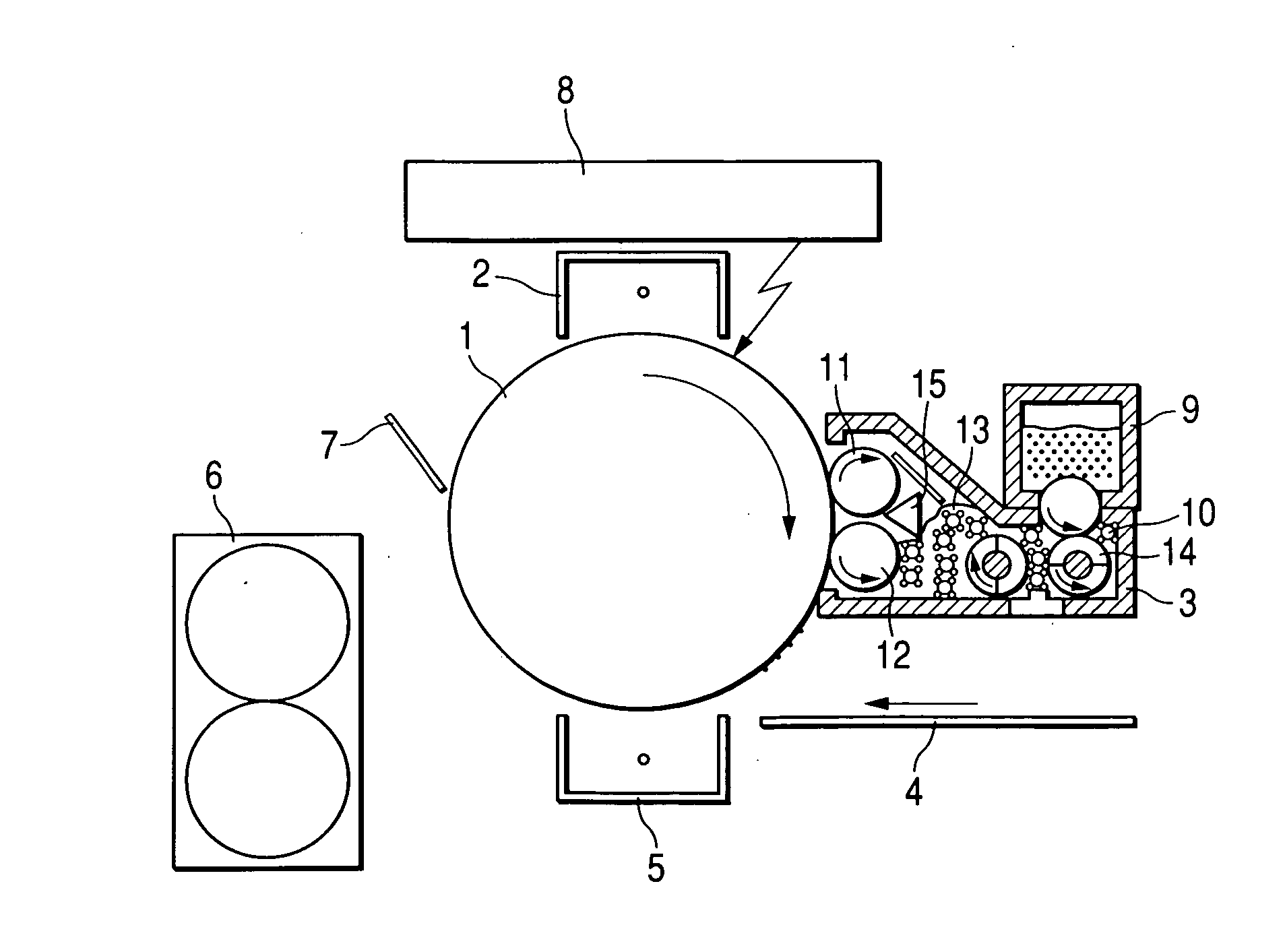
BACKGROUND OF THE INVENTION [0001] 1. Field of the Invention [0002] The present invention relates to an image forming apparatus for visualizing an electrostatic latent image formed in such a process as an electrophotographic process, an electrostatic printing process and an electrostatic recording process. [0003] 2. Description of the Related Art [0004] According to the colorization of an image forming apparatus in recent years, a non-magnetic one-component color toner using no magnetic carrier is often used in general-purpose color printers, and a magnetic brush developing method using a two-component developer is generally employed in high-speed printers. [0005] In the electrophotographic process, a photoconductive photoreceptor is charged and exposed to form an electrostatic latent image on the photoreceptor. The electrostatic latent image is then developed with a toner in a fine particle form including a colorant and a resin as a binder. The resulting toner image is transferred ...

Claims


Application Information

Patent Timeline
IPC IPC(8): G03G9/08G03G9/09G03G15/09
CPCG03G15/09
Inventor YAGUCHI, SHIGENORIKOBAYASHI, JUNJIOUCHI, HIROBUMIHOKKYO, TOMONARI
Owner RICOH KK
Learn More