Fuel supply apparatus for internal combustion engine
- Summary
- Abstract
- Description
- Claims
- Application Information
AI Technical Summary
Benefits of technology
Problems solved by technology
Method used
Image
Examples
first embodiment
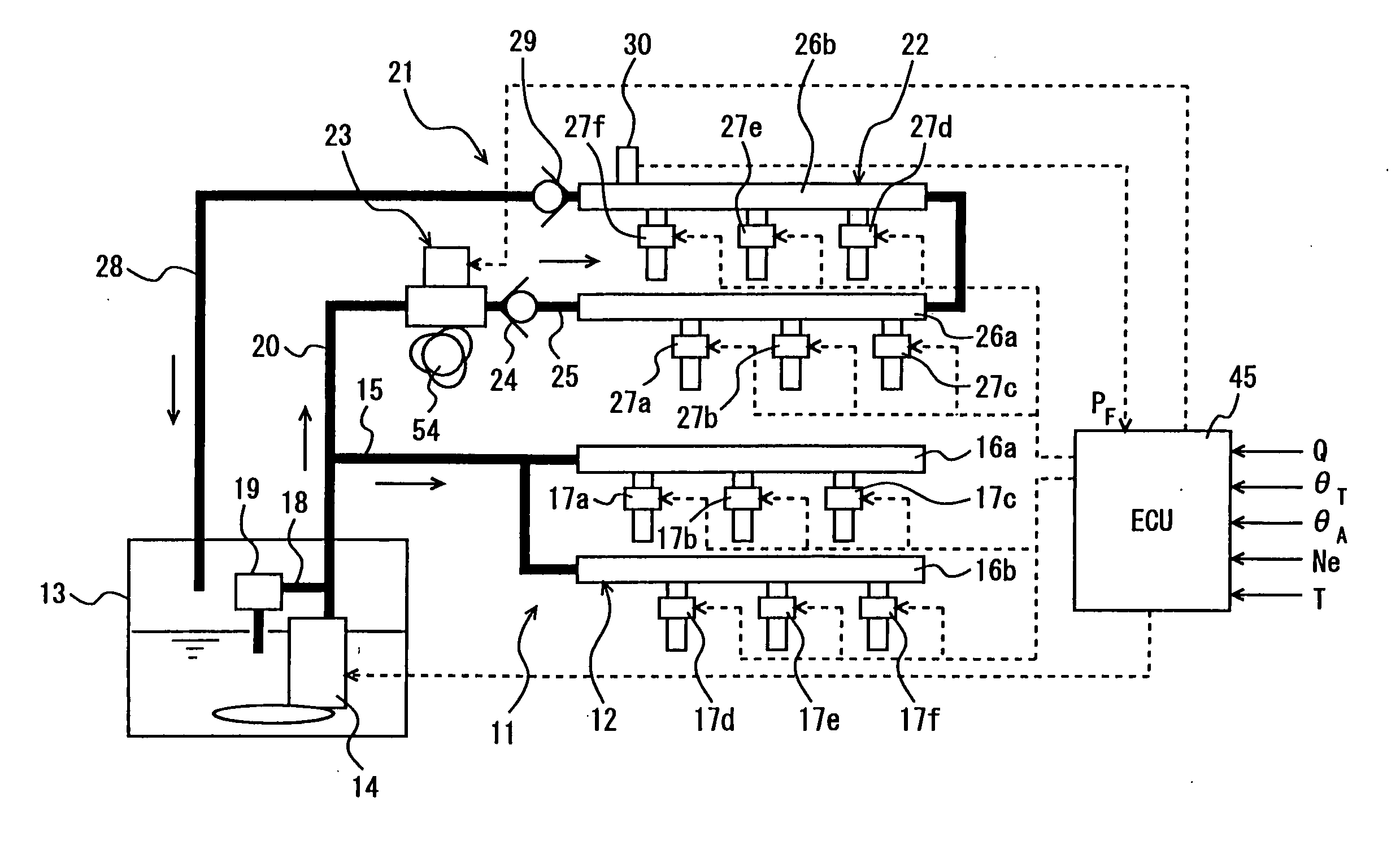
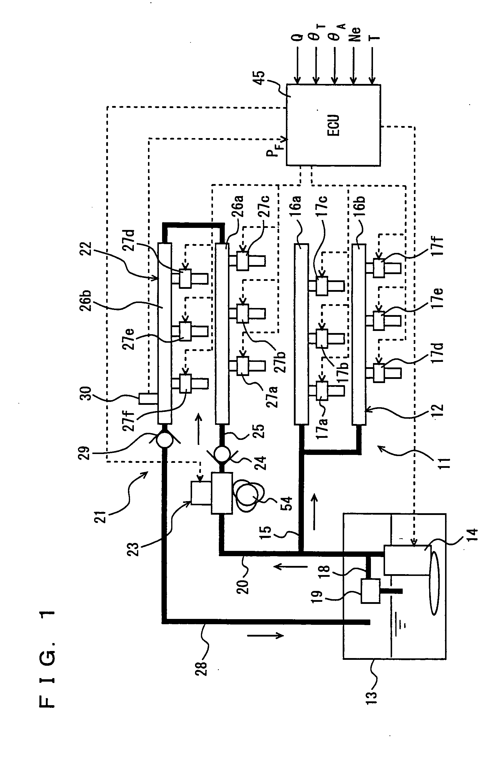
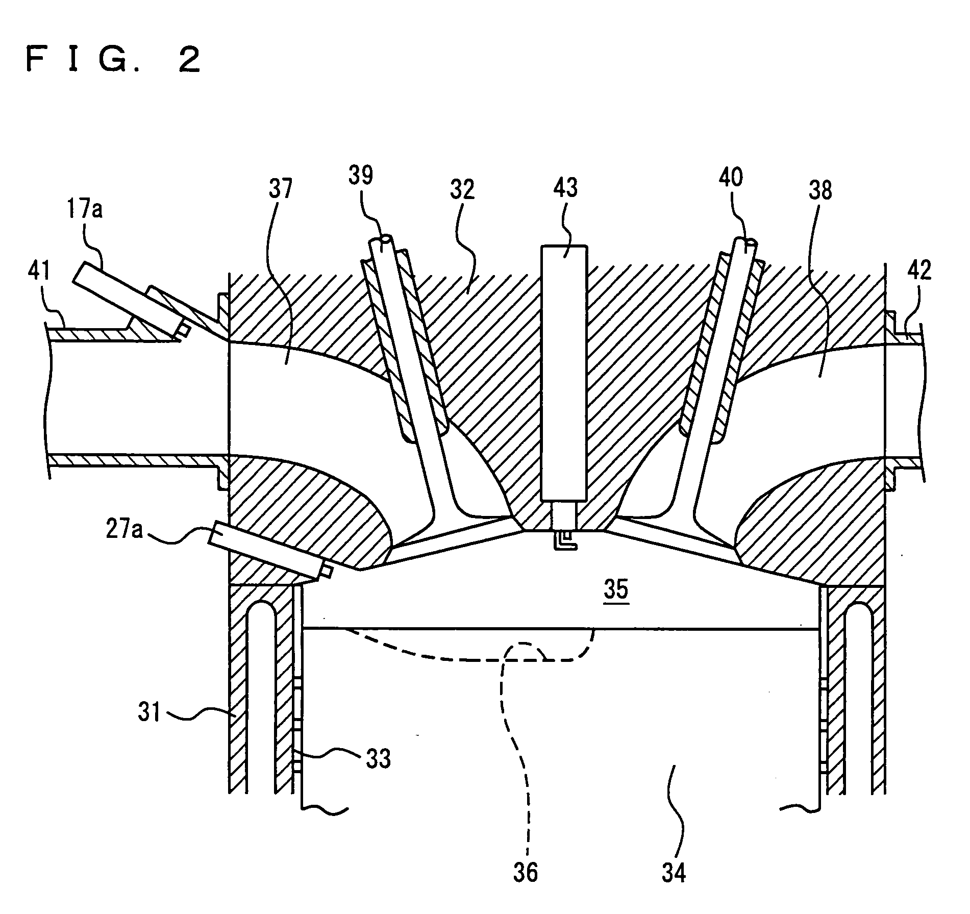
[0029]FIG. 1 schematically shows a fuel supply apparatus for an internal combustion engine according to a first embodiment of the present invention. FIG. 2 shows a main part of the internal combustion engine of the first embodiment. FIG. 3 shows a configuration of a high-pressure pump incorporated in the fuel supply apparatus for the internal combustion engine of the first embodiment, and FIG. 4 is a time chart illustrating the operation of the high-pressure pump. FIGS. 5A and 5B schematically show operating states of the high-pressure pump. FIG. 6 schematically shows pulsation of fuel pressure and order of ignition in a first fuel supply system.
[0030] The internal combustion engine according to the first embodiment of the present invention is a V-type 6-cylinder gasoline engine. A fuel supply apparatus for this engine, as shown in FIG. 1, includes a low-pressure fuel supply system 11 serving as the first fuel supply system for transferring a low-pressure fuel, and a high-pressure ...
second embodiment
[0055]FIG. 7 is a graph showing control regions in a fuel supply apparatus for an internal combustion engine according to a second embodiment of the present invention, and FIG. 8 is a flowchart of fuel injection control in the fuel supply apparatus of the second embodiment. The members having functions similar to those described in the previous embodiment have the same reference characters allotted, and description thereof will not be repeated.
[0056] The configuration of the fuel supply apparatus for an internal combustion engine of the second embodiment is substantially the same as that of the first embodiment. As shown in FIG. 1, it is constituted of low-pressure fuel supply system 11 for applying pressure to the fuel with feed pump 14 and supplying the fuel to manifold fuel injection mechanism 12, high-pressure fuel supply system 21 branched from low-pressure fuel supply system 11 and for applying pressure to the low-pressure fuel with high-pressure pump 23 and supplying the res...
third embodiment
[0075]FIG. 9 schematically shows a fuel supply apparatus for an internal combustion engine according to a third embodiment of the present invention, and FIG. 10 is a flowchart illustrating fuel injection control by the fuel supply apparatus of the third embodiment. The members having functions similar to those described in the previous embodiments have the same reference characters allocated, and description thereof will not be repeated.
[0076] The configuration of the fuel supply apparatus for an internal combustion engine according to the third embodiment is substantially the same as those of the first and second embodiments. As shown in FIG. 9, it includes low-pressure fuel supply system 11 for applying pressure to the fuel with feed pump 14 and supplying the fuel to manifold fuel injection mechanism 12, and high-pressure fuel supply system 21 branched from low-pressure fuel supply system 11 and for applying pressure to the low-pressure fuel with high-pressure pump 23 and supplyi...
PUM
 Abstract
Description
Claims
Application Information
 - R&D
- Intellectual Property
- Life Sciences
- Materials
- Tech Scout
- Unparalleled Data Quality
- Higher Quality Content
- 60% Fewer Hallucinations
Browse by: Latest US Patents, China's latest patents, Technical Efficacy Thesaurus, Application Domain, Technology Topic, Popular Technical Reports.
© 2025 PatSnap. All rights reserved.Legal|Privacy policy|Modern Slavery Act Transparency Statement|Sitemap|About US| Contact US: help@patsnap.com


