
Cyclone type dirt separator and electric vacuum cleaner

a technology of electric vacuum cleaner and separator, which is applied in the direction of suction cleaner, reversed direction vortex, cleaning filter means, etc., can solve the problems of poor efficiency, short service life, and quick blockage of filter,

Inactive Publication Date: 2005-12-08
IZUMI PROD CO
View PDF8 Cites 3 Cited by
  • Summary
  • Abstract
  • Description
  • Claims
  • Application Information

AI Technical Summary

Benefits of technology

[0011] Accordingly, the first object of the present invention is to provide a cyclone type dirt separator which assuredly prevents the entrainment of dirt accumulated in the contaminant collecting trough or dust collecting part by spiral flow of air, thus preventing the exhaust of entrained dirt and intake of such dirt into the cleaner main body.
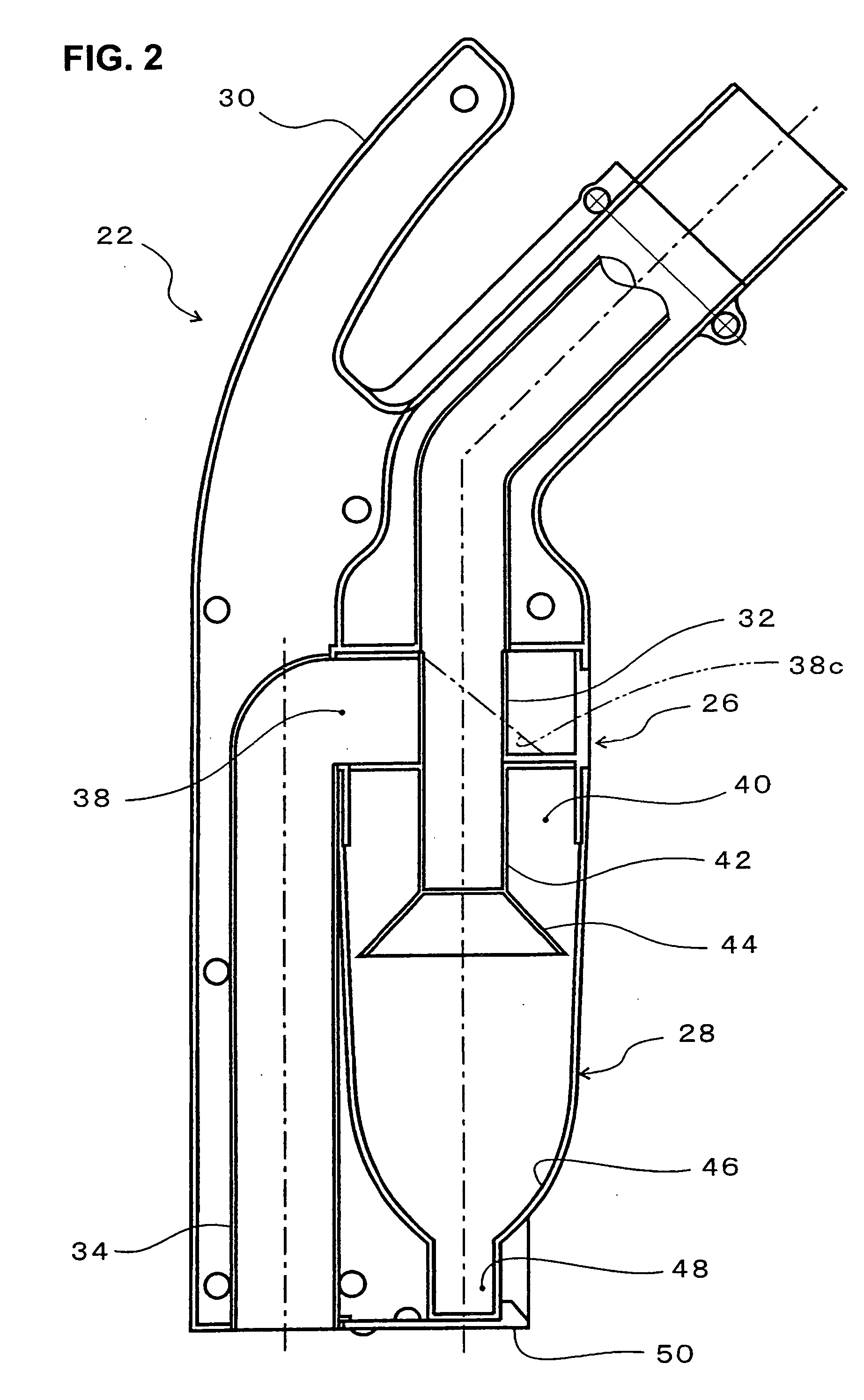
[0017] In this structure of the present invention, since the recessed portion is formed in the vicinity of the center of the inside bottom of the dirt collection chamber, the dirt that enters the dirt collection chamber is conducted into the inside bottom surface and is collected in the recessed portion. In addition, even if a spiral flow is generated in the dirt collection chamber, since this spiral flow tends not to enter the sunken recessed portion, no entrainment of the dirt accumulated in the recessed portion occurs, and dirt in the vicinity of the inside bottom likewise tends not to become entangled and entrained with the dirt accumulated in this recessed portion. Accordingly, dirt that has once entered the dirt collection chamber is prevented from being discharged from the exhaust tube, so that the need for frequent cleaning of the filter inside the cleaner main body is eliminated.
[0024] Accordingly, in the electric vacuum cleaner of the present invention, dirt that has once entered the dirt collection chamber of the cyclone type dirt separator is prevented from being discharged from the exhaust tube, and the need for frequent cleaning of the filter inside the cleaner main body is eliminated.
[0025] In the cyclone type dirt separator of the present invention, the separating section may comprise an exhaust tube, which is disposed substantially in coaxial with the central axis of the spiral of the spiral flow, whose lower end is closed off, and which exhausts air via the exhaust openings in the circumferential surface; and the dirt collection chamber may have a substantially tubular shape that extends downward while surrounding this exhaust tube. In this case, the dirt that is separated by the centrifugal force arising from the spiral flow can be conducted into the inside bottom of the dirt collection chamber with good efficiency, so that the dirt separation is done efficiently. Furthermore, one part (the upper part) of the dirt collection chamber surrounds the exhaust tube and forms an integral unit with the separating section, thus generating a spiral current of air; accordingly, this structure contributes the overall size reduction.
[0026] Furthermore, with a substantially flange-form baffling plate which narrows the air flow path between this baffling plate and the inside wall of the dirt collection chamber, the entry of the spiral flow into the inside bottom of the dirt collection chamber is prevented, so that the entrainment of dirt accumulated in this inside bottom and the outflow of such dirt together with the exhaust can be much more securely prevented.
[0028] The recessed portion can be of a substantially cylindrical shape with a closed bottom. However, the present invention is not limited to this structure, and a square tubular shape recessed portion that has a closed bottom or the like can be also used. By way of setting the diameter of the opening of the recessed portion at approximately ½ to ⅓ of the diameter near the center of the dirt collection chamber, the intrusion of the spiral flow can be sufficiently cut off while maintaining the capacity (volume) of the recessed portion at a large value.

Problems solved by technology

In collection of the dirt, if relatively large pieces of dirt such as paper debris, sludge and the like are contained in large quantities in the dirt that is sucked in, the filter quickly becomes clogged, so that the suction capacity soon drops.
Accordingly, the filter must be cleaned frequently, and this frequent filter cleaning is in fact a problem of poor efficiency.
This dirt causes clogging of the filter of the cleaner main body.
However, a spiral flow would be generated inside the dust collecting part according to the amount of suction air, so that dirt may be entrained; and secure prevention of the entrainment of dirt in the dust collecting part is difficult.
Furthermore, since the dust collecting part is installed separately from the dust separating section, the total length of the structure increases, causing a problem of increased size of the apparatus.

Method used


Image

  • Cyclone type dirt separator and electric vacuum cleaner
  • Cyclone type dirt separator and electric vacuum cleaner
  • Cyclone type dirt separator and electric vacuum cleaner

Examples


Embodiment Construction

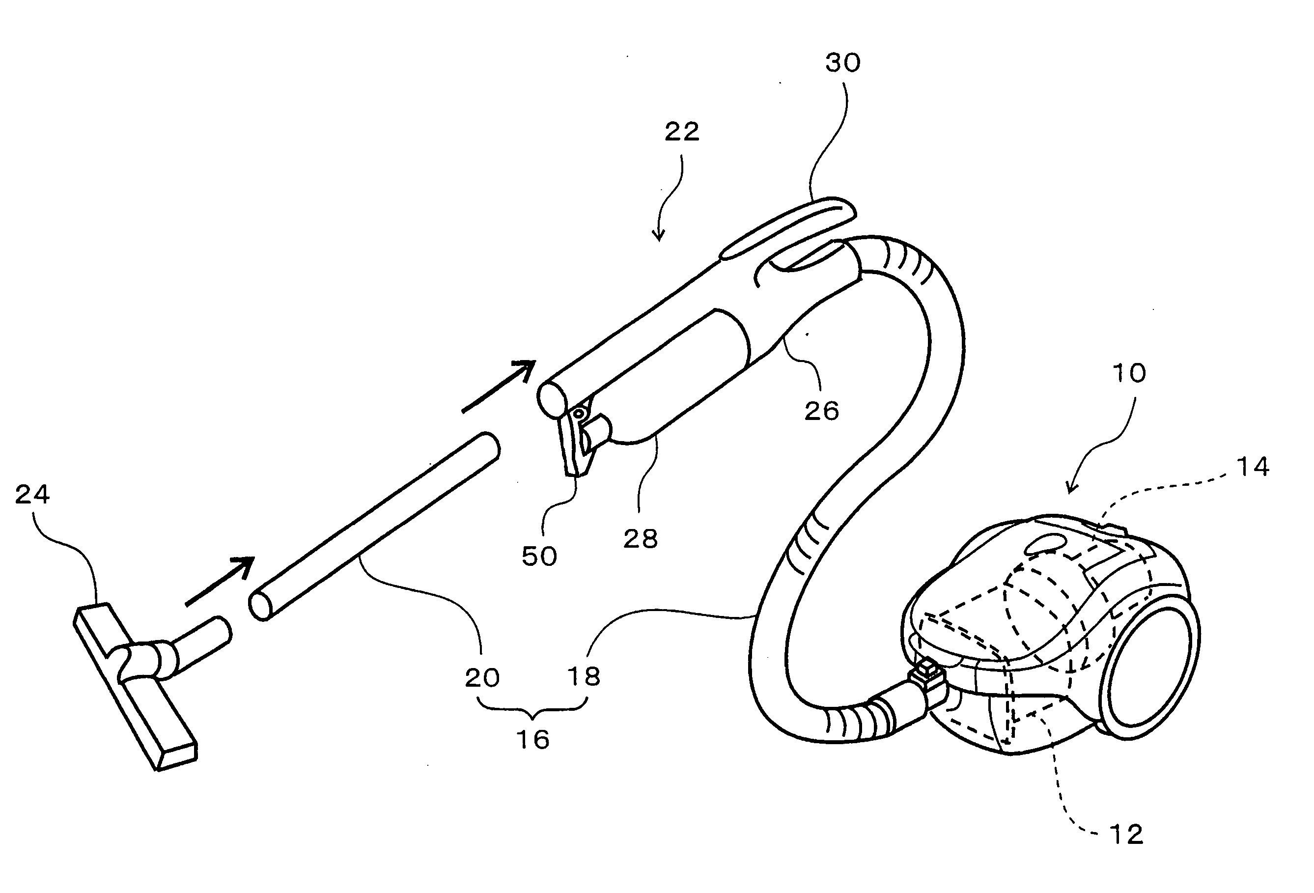
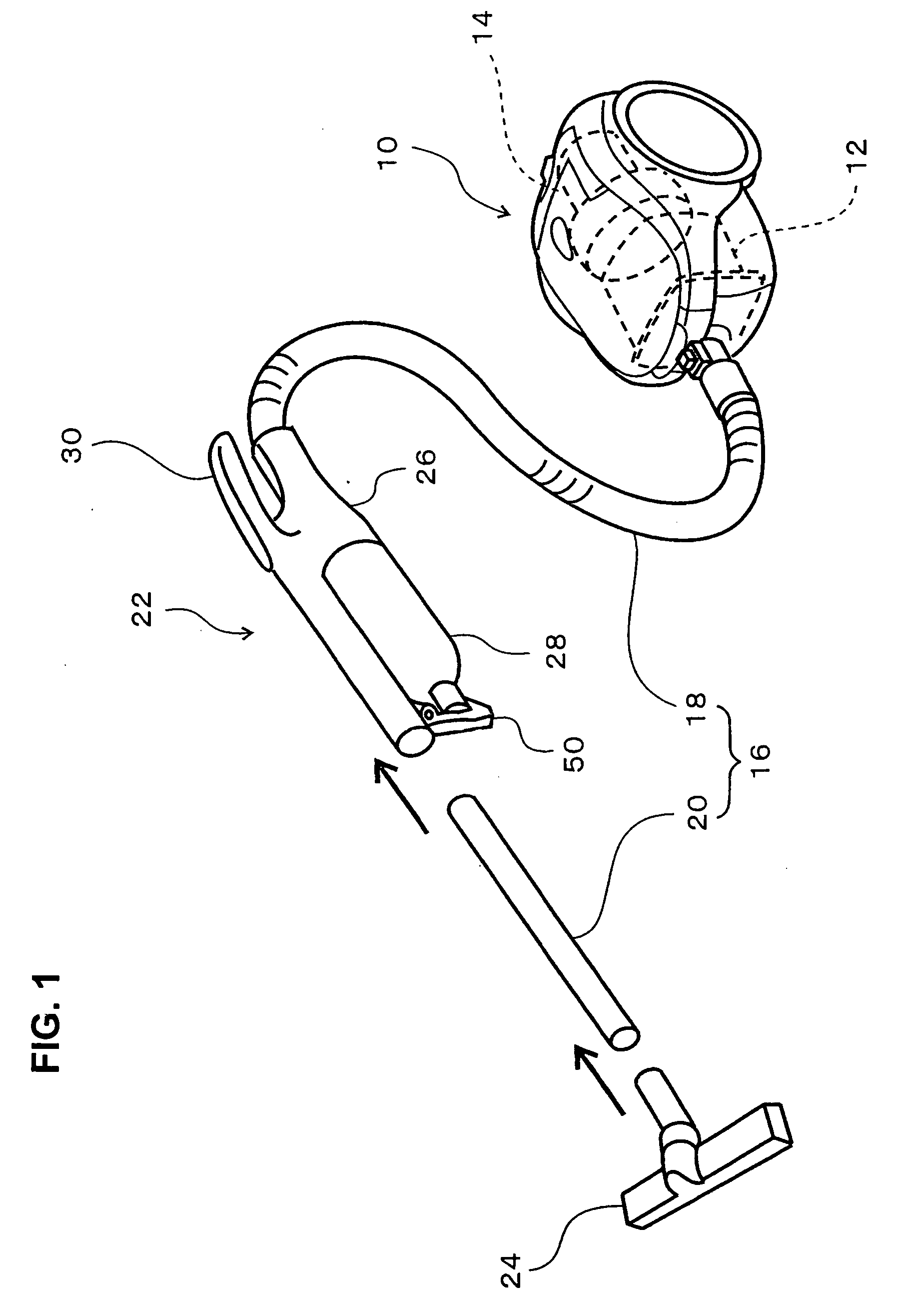
[0036] In FIG. 1, the reference numeral 10 is a cleaner main body, and this cleaner main body 10 is equipped with a filter 12 and an electrically driven air blower 14. A suction tube 16 connected to the cleaner main body 10 is comprised of a flexible tube 18 and an extension tube 20, and a cyclone type dirt separator 22 is provided at an intermediate point of this suction tube 16. The electrically driven air blower 14 generates a suction force by rotating a fan (not shown) at high speed with an electric motor (not shown).

[0037] The electric vacuum cleaner 10 is indeed usable without a cyclone type dirt separator 22; and in this case, the flexible tube 18 (or the forward end of the flexible tube 18) and the extension tube 20 (or the rear end of the extension tube 20) are directly connected to each other to form the suction tube 16. When a cyclone type dirt separator 22 is used, the cyclone type dirt separator 22 is interposed between the flexible tube 18 and the extension tube 20. I...


PUM


Abstract

A cyclone type dirt separator disposed at an intermediate point of an suction tube which connects the suction fitting and the cleaner main body of an electric vacuum cleaner, the dirt separator including: a dirt separating section which causes the suction air to undergo a spiral flow and conducts air from the vicinity of the center of this spiral flow to the cleaner main body, a dirt collection chamber which is attached to the dirt separating section from below and causes the dirt separated from the spiral flow to drop so that the dirt is collected inside the dirt collection chamber, and a recessed portion which is formed in the vicinity of the inside bottom center of the dirt collection chamber so as to be recessed downward.

Description

BACKGROUND OF THE INVENTION [0001] 1. Technical Field [0002] The present invention relates to a cyclone type dirt separator which is provided at an intermediate point of the suction tube of an electric vacuum cleaner and further relates to an electric vacuum cleaner that uses such a separator. [0003] 2. Description of the Related Art [0004] In typical electric vacuum cleaners, suction air that involves dirt that is sucked in via a suction fitting (suction nozzle) is led to the cleaner main body via a suction tube. Here, the suction air that contains dirt passes through a filter installed in the cleaner main body, and dirt is collected by this filter. [0005] In collection of the dirt, if relatively large pieces of dirt such as paper debris, sludge and the like are contained in large quantities in the dirt that is sucked in, the filter quickly becomes clogged, so that the suction capacity soon drops. Accordingly, the filter must be cleaned frequently, and this frequent filter cleaning...

Claims


Application Information

Patent Timeline
IPC IPC(8): A47L9/16B04C5/185
CPCA47L9/1608A47L9/1683A47L9/1666A47L9/165A47L9/16A47L9/10
Inventor SHIMIZU, TETSUHIKO
Owner IZUMI PROD CO
Learn More