System, method and program product for extending range of a bidirectional data communication bus

a data communication and system technology, applied in the field of data communication, can solve the problems of specific integrated circuit technology (asic), field programmable gate array (fpga), and existing complex programmable logic devices (cpld), and achieve the effect of not directly supporting implementation of internal bidirectional signals and not allowing two of these pins to be directly tied together

Inactive Publication Date: 2005-11-24
IBM CORP
View PDF13 Cites 12 Cited by
  • Summary
  • Abstract
  • Description
  • Claims
  • Application Information

AI Technical Summary

Benefits of technology

[0011] Further, additional features and advantages are realized through the techniques of the present invention. Other embodiments and aspects of the invention are described in detail herein and are considered a part of the claimed invention.

Problems solved by technology

Existing complex programmable logic devices (CPLD), field programmable gate array (FPGA), and application specific integrated circuit (ASIC) technologies do not directly support implementation of internal bidirectional signals without the use of a dedicated direction control signal.
However, these architectures do not allow for two of these pins to be directly tied together while maintaining a truly asynchronous bidirectional data path.
The only existing solution to this unique problem is the introduction of a data direction control signal, which makes asynchronous bidirectional communication impossible.
This can arise because multiple devices may share the same address or there may not be enough addresses to accommodate the number of devices.
Analog switches are large and expensive and this limits the complexity of the switching which can be easily achieved.
As a further issue, a bidirectional data communication bus implemented on a single transmission line typically has a limited data communication range due to intrinsic capacitance established in the transmission line as the length increases.

Method used


Image

  • System, method and program product for extending range of a bidirectional data communication bus
  • System, method and program product for extending range of a bidirectional data communication bus
  • System, method and program product for extending range of a bidirectional data communication bus

Examples


Embodiment Construction

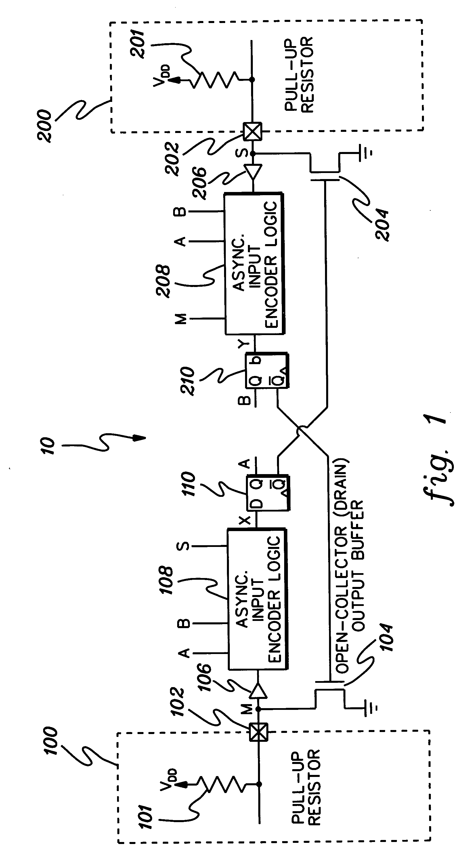
[0021]FIG. 1 depicts an exemplary bidirectional communications system 10 between two devices, shown as first device 100 and second device 200. The designations first and second are for identification purposes only. The first and second designations do not indicate that one device has access priority to the communication bus or controls all communications between the two devices. Each device 100 and 200 includes a bidirectional input / output (I / O) pin 102 and 202, respectively. The input / output pins are pulled to logic high by pull-up resistors 101 and 201, respectively.

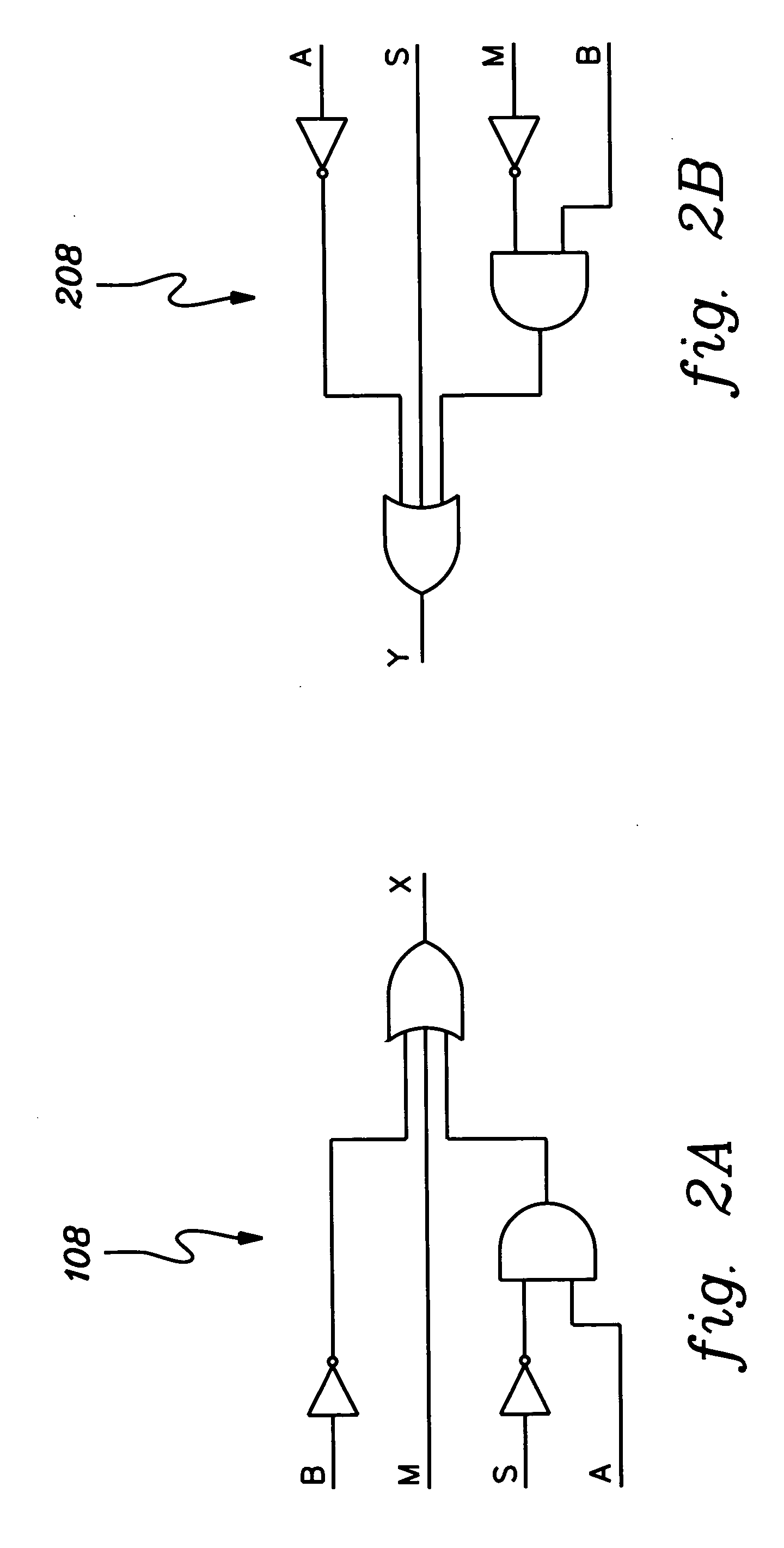
[0022] The communication system includes a first bus driver 104 and a second bus driver 204. The first signal M is provided to an input buffer 106 and then to first asynchronous encoder logic 108. The first asynchronous encoder logic 108 receives the first signal M, current first state A, current second state B and second signal S and generates a next first state X. The next first state X is provided to gate 110 (e.g....


PUM


Abstract

A communication system, method and program product are provided for establishing an extended bidirectional communication bus between a first device and a second device. The communication system includes decomposition logic for decomposing a single line, bidirectional data communication bus into a unidirectional transmit data communication bus and a unidirectional receive data communication bus. A differential communication subsystem is connected to the two unidirectional buses for extending the length thereof, and recomposition circuitry is connected to the differential communication subsystem for recombining the extended unidirectional transmit data communication bus and the extended unidirectional receive data communication bus to reestablish the single line, bidirectional data communication bus. The decomposition logic, differential communication subsystem and recomposition circuitry are implemented transparent to the first device and the second device and without use of a data direction control line.

Description

Cross Reference To Related Application [0001] This application contains subject matter which is related to the subject matter of the following application, which is assigned to the same assignee as this application and which is hereby incorporated herein by reference in its entirety: [0002]“Method and System For Providing Bidirectional Asynchronous Communication”, Barus et al., Ser. No. 10 / 668,488 filed Mar. 23, 2003.TECHNICAL FIELD [0003] The present invention relates to data communication, and in particular, to a system, method and program product for providing an extended bidirectional communication bus between two devices. Embodiments of the invention use a state machine design that may be implemented, for example, using discrete logic or programmable logic devices. BACKGROUND OF THE INVENTION [0004] Existing complex programmable logic devices (CPLD), field programmable gate array (FPGA), and application specific integrated circuit (ASIC) technologies do not directly support imp...

Claims


Application Information

Patent Timeline
Patent Type & Authority Applications(United States)
IPC IPC(8): H03K3/00H03K19/0175H04L5/14H04L5/16H04L12/40H04L25/22
CPCH03K19/01759H04L25/22H04L5/16H04L5/14
Inventor BEHRENDT, EILEEN M.BIAMONTE, JEFFREY B.HARRINGTON, RAYMOND J.TRIFILO, TIMOTHY M.
Owner IBM CORP
Why Eureka
Try Eureka