Oscillation detecting apparatus and test apparatus

a detection apparatus and oscillation detection technology, applied in the direction of power supply testing, instruments, pulse technique, etc., can solve the problems of oscillation detection apparatus not being able to detect oscillation correctly, and affecting the detection accuracy of oscillation detection apparatus

Inactive Publication Date: 2005-11-24
ADVANTEST CORP
View PDF7 Cites 9 Cited by
  • Summary
  • Abstract
  • Description
  • Claims
  • Application Information

AI Technical Summary

Benefits of technology

[0045] As obvious from the above description, according to the present invention, it is possible to reduce the incorrect detection of the oscillation of the signal and detect the oscillation of the signal efficiently.

Problems solved by technology

When the power supply voltage oscillates, it is desirable to detect the oscillation of the power supply voltage because there is concern that the test apparatus or the electronic device might be damaged.
However, the oscillation detecting apparatus of such a configuration may detect the signal, whose amplitude is large, as if it is in oscillation, even though it is not in oscillation, because the integration value of the signal becomes large.
For example, in a test apparatus, when the fluctuation of a signal level is large, e.g. the output of the power supply voltage is started or stopped, the amplitude of the output signal of a filter in the oscillation detecting apparatus becomes large, so that the oscillation detecting apparatus detects the oscillation incorrectly.

Method used


Image

  • Oscillation detecting apparatus and test apparatus
  • Oscillation detecting apparatus and test apparatus
  • Oscillation detecting apparatus and test apparatus

Examples


Embodiment Construction

[0020] The invention will now be described based on the preferred embodiments, which do not intend to limit the scope of the present invention, but exemplify the invention. All of the features and the combinations thereof described in the embodiment are not necessarily essential to the invention.

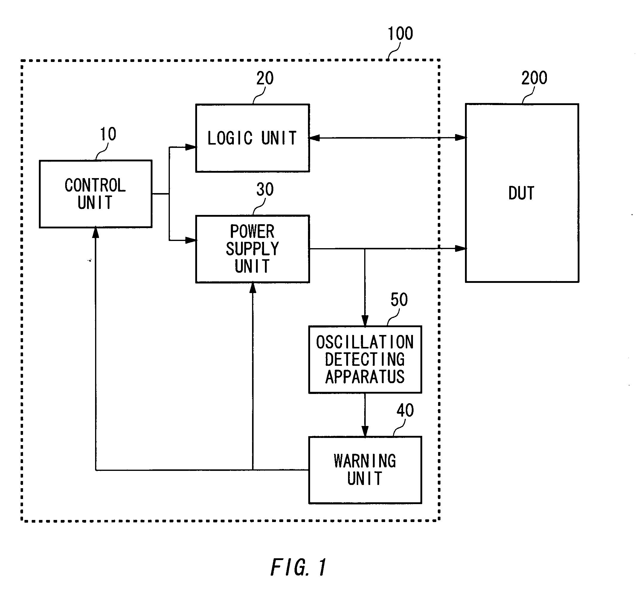
[0021]FIG. 1 shows an example of the configuration of a test apparatus 100 according to an embodiment of the present invention. The test apparatus 100 for testing an electronic device 200 such as a semiconductor circuit includes a control unit 10, a logic unit 20, a power supply unit 30, a warning unit 40, and an oscillation detecting apparatus 50.

[0022] The logic unit 20 inputs a test pattern for the test of the electronic device 200 into the electronic device 200 and determines pass or fail of the electronic device based on an output signal outputted from the electronic device 200.

[0023] The power supply unit 30 provides the electronic device 200 with a power supply voltage and a power ...


PUM


Abstract

An oscillation detecting apparatus for detecting oscillation of a signal includes a high pass filter for generating an alternating current signal from which a direct current component of the signal is removed, a slicing circuit for generating a limit signal which results from restricting an amplitude level of the alternating current signal to a level lower than a predetermined level, an integration circuit for integrating a waveform of the limit signal during a predetermined period, and a comparator for detecting whether or not the signal oscillates based on a value of the waveform integrated by the integration circuit.

Description

BACKGROUND OF THE INVENTION [0001] 1. Field of the Invention [0002] The present invention relates to an oscillation detecting apparatus for detecting the oscillation of a signal and a test apparatus for testing an electronic device. [0003] 2. Description of the Related Art [0004] Conventionally, in a test apparatus for testing an electronic device such as a semiconductor circuit, a source power is supplied to the electronic device. In some cases, the power supply voltage may oscillate according to the characteristics of the electronic device connected to the test apparatus as a load. When the power supply voltage oscillates, it is desirable to detect the oscillation of the power supply voltage because there is concern that the test apparatus or the electronic device might be damaged. [0005] A conventional oscillation detecting apparatus includes a filter for removing a direct current component of a given signal, an absolute value circuit for rectifying the signal, an integration cir...

Claims


Application Information

Patent Timeline
IPC IPC(8): G01R19/00G01R19/165G01R31/26G01R31/28
CPCG01R19/1658G01R19/0007G01R31/28G01R31/26
Inventor KIMURA, HIROKI
Owner ADVANTEST CORP
Why Eureka
Try Eureka