
Method for manufacturing speaker-use center cap

a center cap and speaker technology, applied in the direction of transducer diaphragms, electromechanical transducers, instruments, etc., can solve the problems of increasing production costs, difficult to provide uniform contact, and giving possibility of occurrence of changes in acoustic characteristics, so as to increase the number of manufacturing steps and increase the production cost

Inactive Publication Date: 2005-11-24
PIONEER CORP +1
View PDF6 Cites 31 Cited by
  • Summary
  • Abstract
  • Description
  • Claims
  • Application Information

AI Technical Summary

Benefits of technology

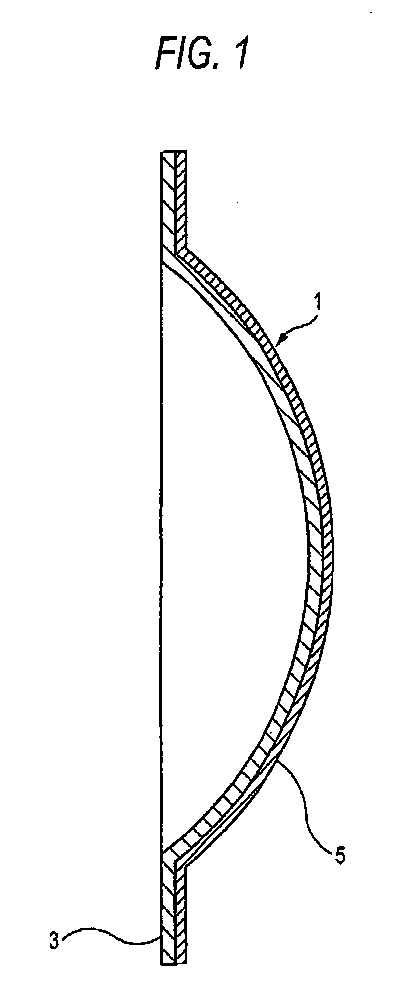
[0019] However, the above conventional method has a problem that the number of manufacturing steps is increased because of the step of independently molding the second cap member layer 5, thus increasing the production cost.

Problems solved by technology

However, the above conventional method has a problem that the number of manufacturing steps is increased because of the step of independently molding the second cap member layer 5, thus increasing the production cost.
Further, when the second cap member layer 5 molded is set in a die for injection-molding the first cap member layer 3 (hereinafter referred to as an injection-molding die), or when the first cap member layer 3 and the second cap member layer 5 which have been individually made are stacked, it was difficult to provide uniform contact over the entire region of a stacking plane because of a fine size error therebetween and was impossible to ensure a uniform physical property over the entire region of the center cap, thus giving possibility of occurrence of changes in the acoustic characteristic.
This makes it difficult to make the printing with high accuracy.
Problems that the present invention intends to solve are the problems involved in the above conventional technique, for example, a problem of an increase in cost due to the increase in the number of manufacturing steps, a problem of partial fluctuation in intimate contact due to a size error between the first cap member layer and the second cap member layer, thus leading to a fluctuating vibrating characteristic, limiting of the material of the surface layer in the case where printing is made on the cap surface.

Method used


Image

  • Method for manufacturing speaker-use center cap
  • Method for manufacturing speaker-use center cap
  • Method for manufacturing speaker-use center cap

Examples


Embodiment Construction

[0036] Now referring to the drawings, a detailed explanation will be given of various preferred embodiments of a method for manufacturing a speaker-use center cap according to this invention.

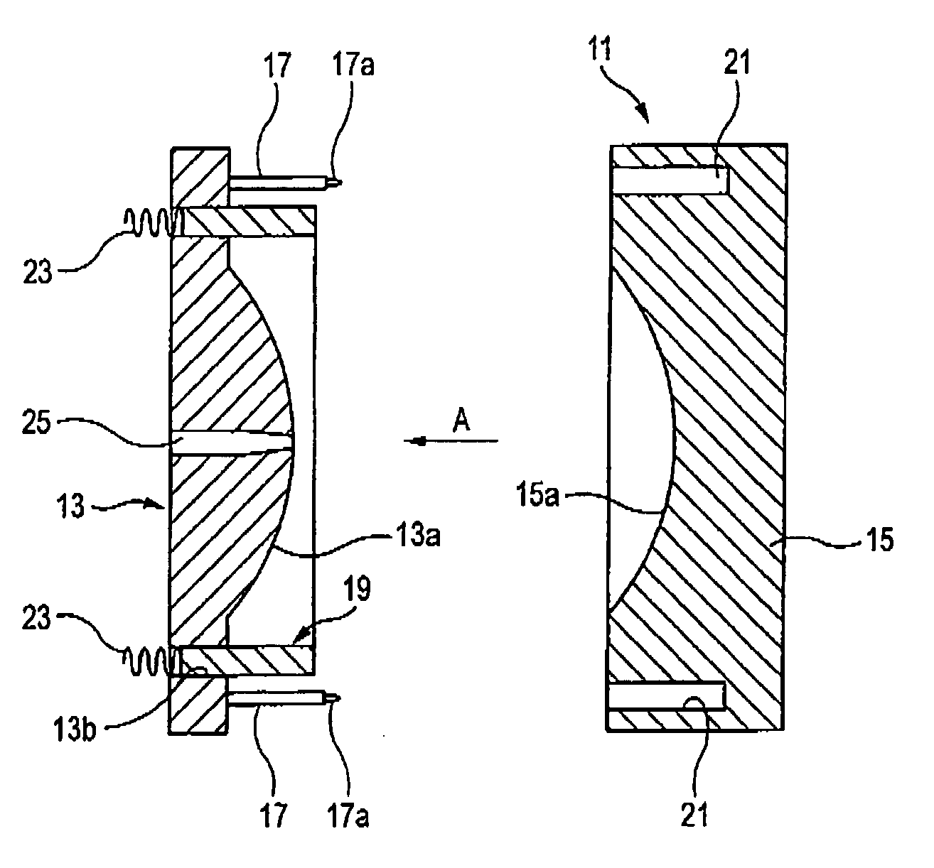
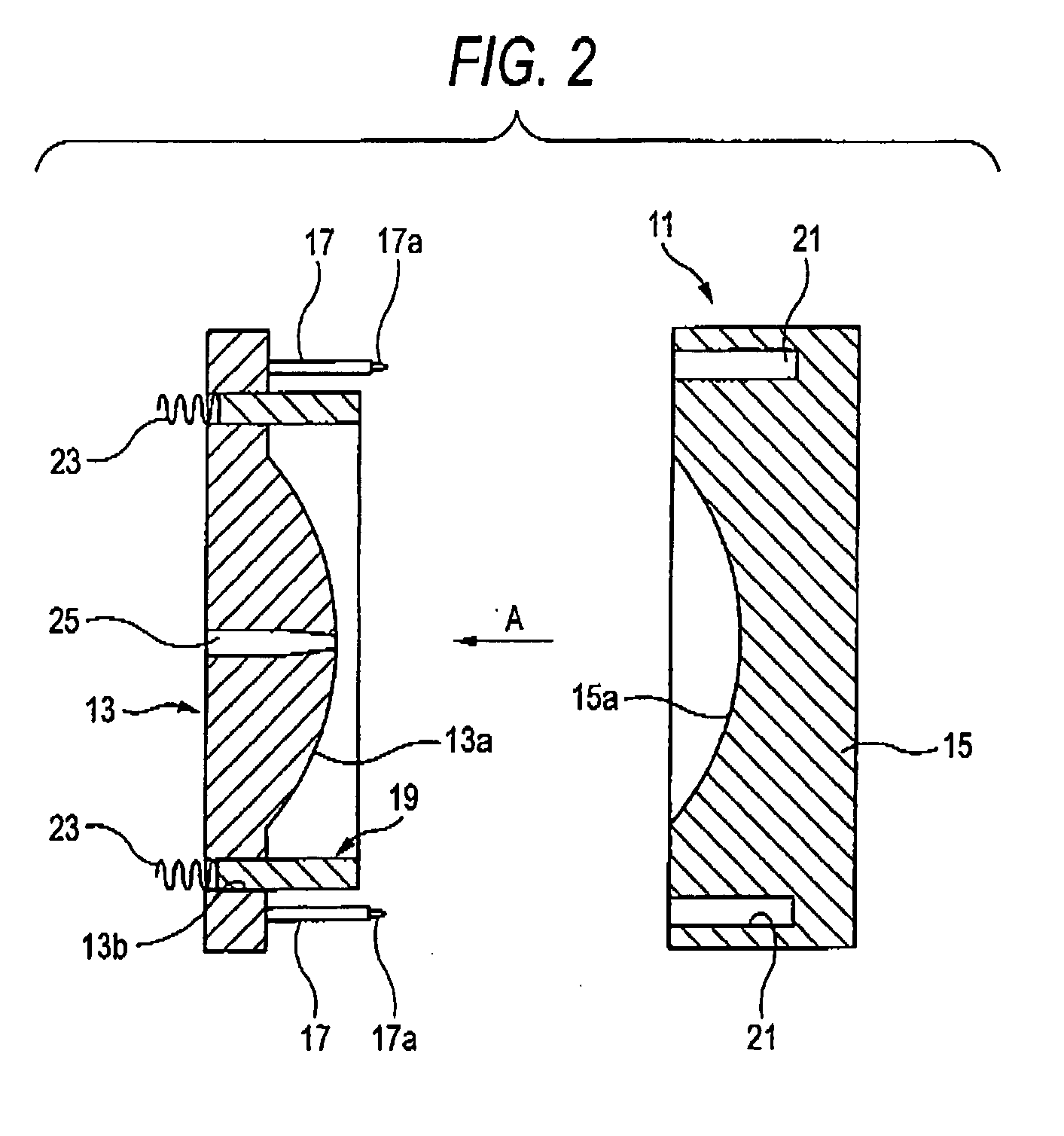
[0037]FIGS. 2 and 3 show an injection-molding die used in an embodiment of a method for manufacturing a speaker-use center cap according to this invention.

[0038] An injection-molding die 11 is used for manufacturing the speaker-use center cap 1 shown in FIG. 1. The injection-molding die 11 consists of a male die part (also simply referred to as a male die) 13 having a bowl or dome-shaped projection 13a formed along the contour of the surface of the speaker-use center cap 1 and a female die part (also simply referred to as a female die) 15 having a bowl or dome-shaped concavity 15a corresponding to the dome-shaped projection 13a.

[0039] One of the male die 13 and the female die 15 is movably supported by a guide member not shown so that the injection molding die 11 can be opened and closed.

[00...


PUM

PropertyMeasurementUnit
Shapeaaaaaaaaaa
Distanceaaaaaaaaaa

Abstract

A method is for manufacturing a speaker-use center cap provided with a first cap member layer of synthetic resin and a second cap member layer layered in intimate contact with the first cap member layer and made of a material different from that of the first cap member layer. The method includes: a pre-molding step of attaching a non-molded sheet-like material which is a raw material of the second cap member layer to a mating surface of one of die parts of an injection molding die and thereafter closing the injection molding die to apply a predetermined cap shape to the sheet-like material; and an injection molding step of injecting the synthetic resin material into the injection molding die closed by the pre-molding step to form the first cap member layer to be intimate contact with the second cap member layer.

Description

[0001] The present disclosure relates to the subject matter contained in Japanese Patent Application No. 2004-148385 filed on May 18, 2005, which is incorporated herein by reference in its entirety. BACKGROUND OF THE INVENTION [0002] 1. Field of the Invention [0003] The present invention relates to a method for manufacturing a center cap for use in a speaker (hereinafter referred to as a speaker-use center cap), and more particularly to a method for manufacturing a center cap for use in a speaker in a multi-layer structure including a first cap member layer of synthetic resin molded in a predetermined shape by injection molding and a second cap member layer (skin layer) layered or stacked in intimate contact on the first cap member layer and made of a different material from the first cap member layer. [0004] 2. Description of the Related Art [0005] In an electrodynamic speaker, which produces sound through amplitude-vibration of a diaphragm by a magnetic circuit, an opening is form...

Claims


Application Information

Patent Timeline
IPC IPC(8): B29C33/12B29C45/14B29L31/38G10K13/00H04R1/02H04R7/00H04R9/02H04R31/00
CPCB29C45/14065B29C45/1418B29C45/14344B29C45/14778B29C2045/14147B29K2277/10B29K2713/00B29K2995/0002H04R1/023H04R31/00
Inventor SATO, SEIYAKOBAYASHI, HIROYUKI
Owner PIONEER CORP
Learn More