
System and process for controlling electronic components in a ubiquitous computing environment using multimodal integration

a multimodal integration and electronic component technology, applied in computing, electrophonic musical instruments, instruments, etc., can solve the problems of high error rate of speech recognition-based control systems, difficult design of good user interfaces, and large increase in the cost of a “single-ui-controlled” environmen

Active Publication Date: 2005-11-17
MICROSOFT TECH LICENSING LLC
View PDF39 Cites 5 Cited by
  • Summary
  • Abstract
  • Description
  • Claims
  • Application Information

AI Technical Summary

Benefits of technology

[0012] In order to control one of the aforementioned electronic components, the component must first be identified to the control system. In general this can be accomplished using the pointing system to identify the desired component by pointing at it, or by employing speech recognition, or both. The advantage of using both is to reinforce the selection of a particular component, even in a noisy environment where the speech recognition system may operate poorly. Thus, by combining inputs the overall system is made more robust. This use of divergent inputs to reinforce the selection is referred to as multimodal integration.
[0019] In regard to the use of simple and short duration gestures, such as for example a single upwards or downwards motion, an opportunity exists to employ a simplified approach to gesture recognition. For such gestures, a recognition strategy can be employed that looks for simple trends or peaks in one or more of the sensor values output by the pointer. For example, pitching the pointer up may be detected by simply thresholding the output of the accelerometer corresponding to pitch. Clearly such an approach will admit many false positives if run in isolation. However, in a real system this recognition will be performed in the context on an ongoing interaction, during which it will be clear to system (and to the user) when a simple pitch up indicates the intent to control a device in a particular way. For example, the system may only use the gesture recognition results if the user is also pointing at an object, and furthermore only if the particular gesture applies to that particular object. In addition, the user can be required to press and hold down the pointer's button while gesturing. Requiring the user to depress the button while gesturing allows the system to easily determine when a gesture begins. In other words, the system records sensor values only after the user depresses the button, and thus gives a natural origin from which to detect trends in sensor values. In the context of gesturing while pointing at an object, this process induces a local coordinate system around the object, so that “up”, “down”, “left” and “right” are relative to where the object appears to the user. For example, “up” in the context of a standing user pointing at an object on the floor means pitching up from a pitched down position, and so on.
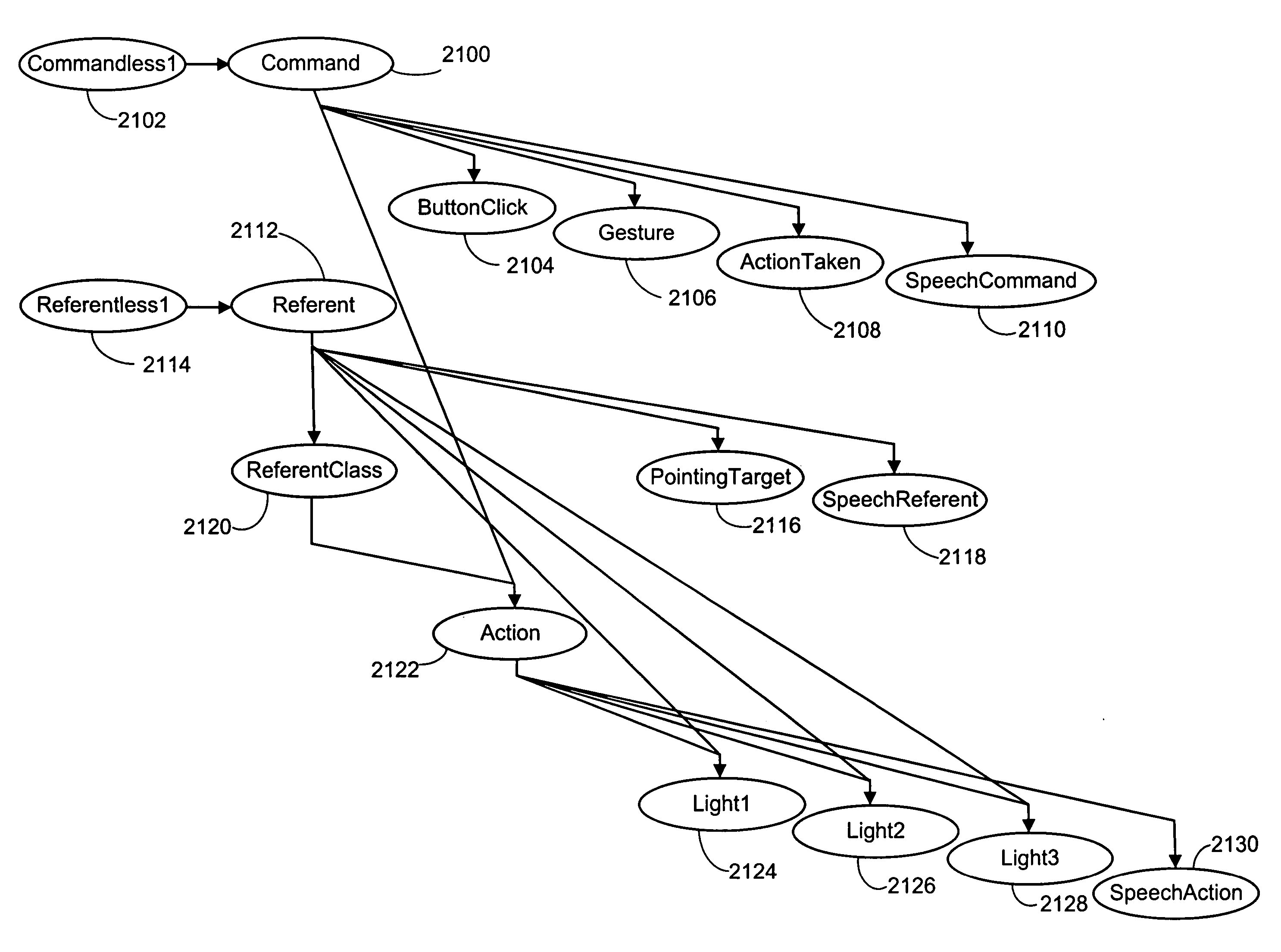
[0020] As discussed above, a system employing multimodal integration would have a distinct advantage over one system alone. To this end, the present invention includes the integration of a conventional speech control system into the gesture control and pointer systems which results in a simple framework for combining the outputs of various modalities such as pointing to target objects and pushing the button on the pointer, pointer gestures, and speech, to arrive at a unified interpretation that instructs a combined environmental control system on an appropriate course of action. This framework decomposes the desired action into a command and referent pair. The referent can be identified using the pointer to select an object in the environment as described previously or using a conventional speech recognition scheme, or both. The command may be specified by pressing the button on the pointer, or by a pointer gesture, or by a speech recognition event, or any combination thereof.
[0023] The Bayes network architecture also allows the state of various devices to be incorporated via the aforementioned device state input nodes. In particular, these nodes provide state information to the action node that reflects the current condition of an electronic component associated with the device state input node whenever the referent node probability distribution indicates the referent is that component. This allows, as an example, the device state input nodes to input an indication of whether the associated electronic component is activated or deactivated. This can be quite useful in situations where the only action permitted in regard to an electronic component is to turn it off if it is on, and to turn it on if it is off. In such a situation, an explicit command need not be determined. For example if the electronic component is a lamp, all that need be known is that the referent is this lamp and that it is on or off. The action of turning the lamp on or off, as the case may be, follows directly, without the user ever having to command the system.

Problems solved by technology

This presents a challenge in designing good user interfaces.
Typically, such devices are limited to one transmission scheme, such as IR or RF, and so can control only electronic components operating on that scheme.
This could add considerably to the cost of a “single UI-controlled” environment.
However, current speech recognition-based control systems typically exhibit high error rates.
This decrease in accuracy occurs for the most part because of the unpredictable and variable noise levels found in a normal operating setting, and the way humans alter their speech patterns to compensate for this noise.
In fact, environmental noise is currently viewed as a primary obstacle to the widespread commercialization of speech recognition systems.
However, it is also desirable to control devices in more complex ways than merely turning them on or off.
However, unless the similarity is great enough, it might be that the pointer movements are random and do not match any of the trained gestures.
Clearly such an approach will admit many false positives if run in isolation.

Method used


Image

  • System and process for controlling electronic components in a ubiquitous computing environment using multimodal integration
  • System and process for controlling electronic components in a ubiquitous computing environment using multimodal integration
  • System and process for controlling electronic components in a ubiquitous computing environment using multimodal integration

Examples


Embodiment Construction

[0046] In the following description of the preferred embodiments of the present invention, reference is made to the accompanying drawings which form a part hereof, and in which is shown by way of illustration specific embodiments in which the invention may be practiced. It is understood that other embodiments may be utilized and structural changes may be made without departing from the scope of the present invention.

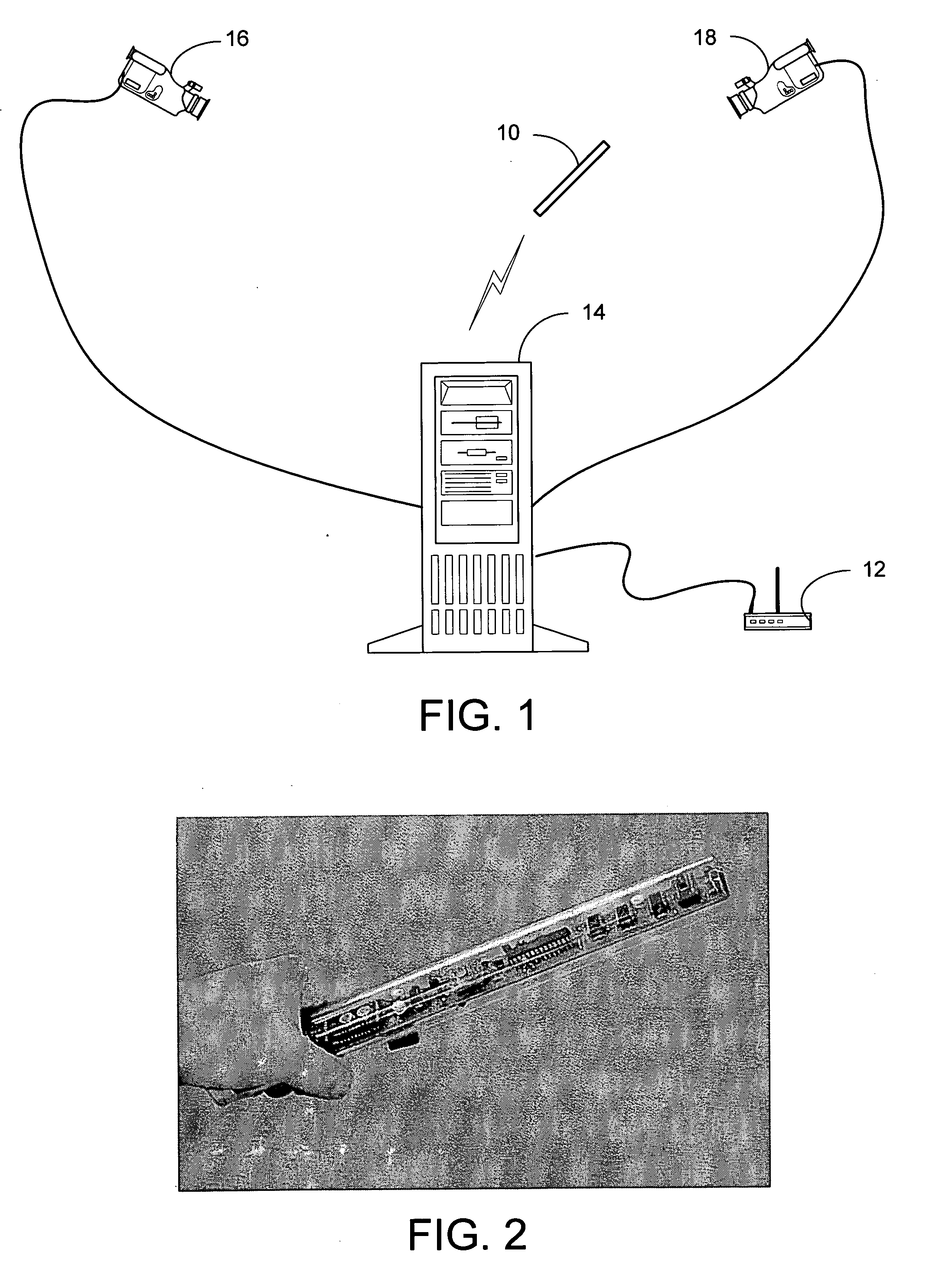
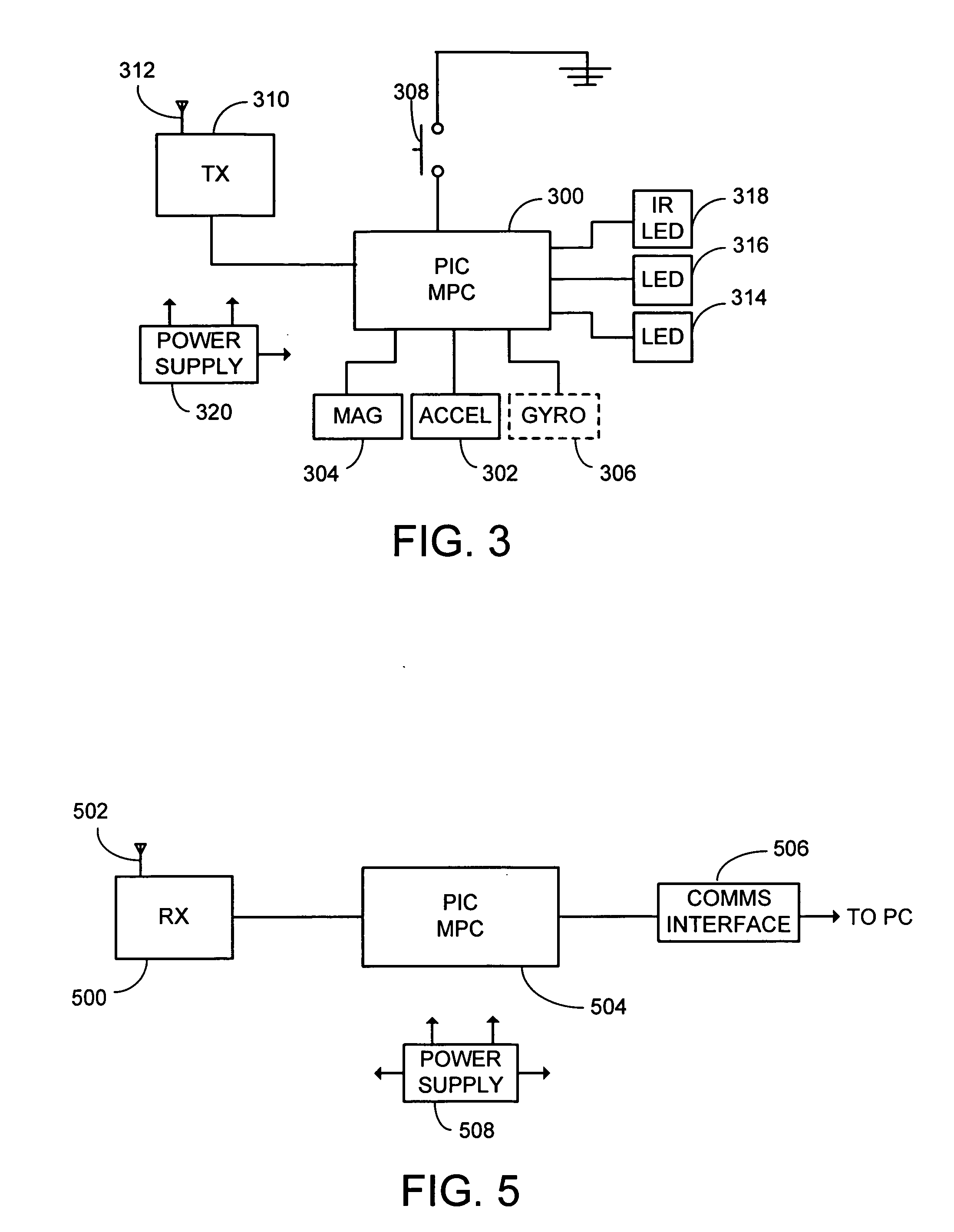
[0047] In general, the present electronic component control system and process involves the integration of a unique wireless pointer-based object selection system, a unique gesture recognition system that employs the wireless pointer, and a conventional speech control system to create a multimodal interface for determining what component a user wants to control and what control action is desired.

[0048] The pointer-based object selection system will be described first in the sections to follow, followed by the gesture recognition system, and finally the integration of t...


PUM


Abstract

The present invention is directed toward a system and process that controls a group of networked electronic components using a multimodal integration scheme in which inputs from a speech recognition subsystem, gesture recognition subsystem employing a wireless pointing device and pointing analysis subsystem also employing the pointing device, are combined to determine what component a user wants to control and what control action is desired. In this multimodal integration scheme, the desired action concerning an electronic component is decomposed into a command and a referent pair. The referent can be identified using the pointing device to identify the component by pointing at the component or an object associated with it, by using speech recognition, or both. The command may be specified by pressing a button on the pointing device, by a gesture performed with the pointing device, by a speech recognition event, or by any combination of these inputs.

Description

CROSS-REFERENCE TO RELATED APPLICATIONS [0001] This application claims the benefit of a previously filed provisional patent application Ser. No. 60 / 355,368, filed on Feb. 7, 2002.BACKGROUND [0002] 1. Technical Field [0003] The invention is related to controlling electronic components in a ubiquitous computing environment, and more particularly to a system and process for controlling the components using multimodal integration in which inputs from a speech recognition subsystem, gesture recognition subsystem employing a wireless pointing device and pointing analysis subsystem associated with the pointing device, are combined to determine what component a user wants to control and what control action is desired. [0004] 2. Background Art [0005] Increasingly our environment is populated with a multitude of intelligent devices, each specialized in function. The modern living room, for example, typically features a television, amplifier, DVD player, lights, and so on. In the near future, ...

Claims


Application Information

Patent Timeline
IPC IPC(8): G06F3/038G08C17/00
CPCG08C2201/50G08C17/00G08C2201/41G08C2201/32G06F3/0346G06F3/038G06F2203/0381G08C2201/31
Inventor WILSON, ANDREW
Owner MICROSOFT TECH LICENSING LLC
Learn More