
Angular flow distribution bottom head

Active Publication Date: 2005-11-17
UNIVATION TECH LLC
View PDF32 Cites 8 Cited by
  • Summary
  • Abstract
  • Description
  • Claims
  • Application Information

AI Technical Summary

Benefits of technology

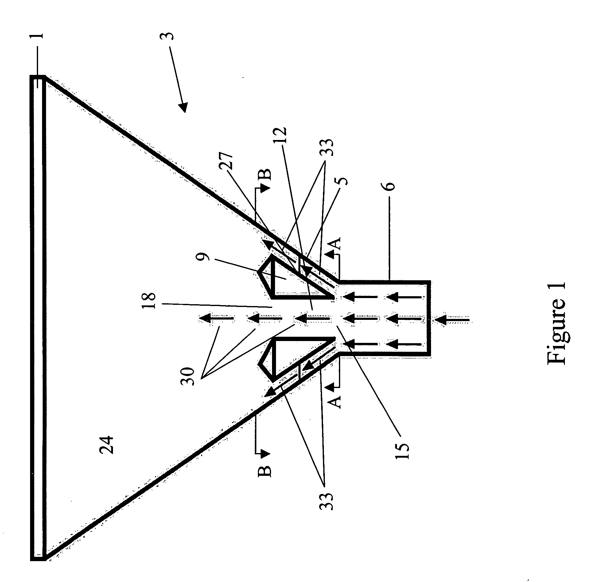
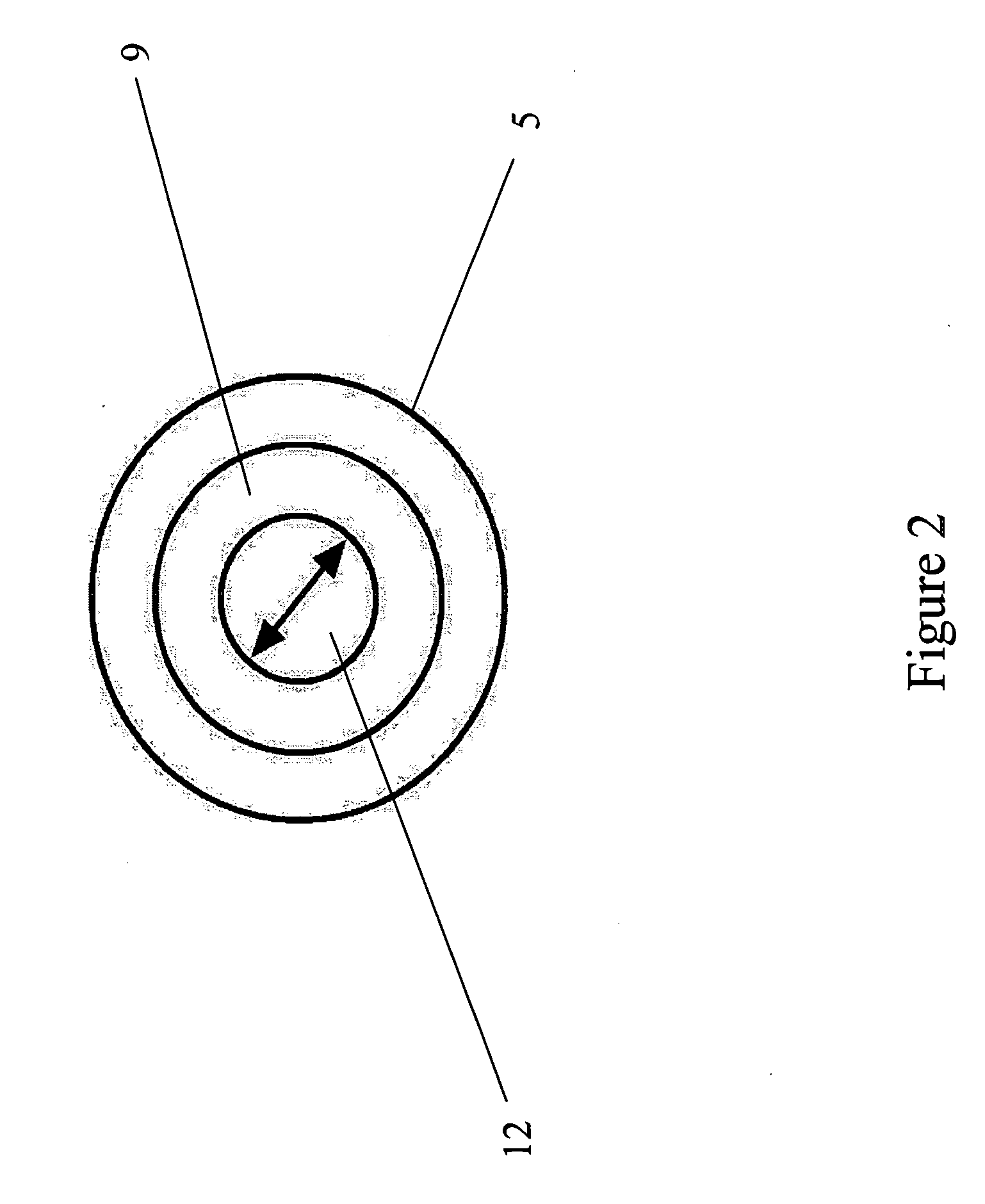
The present invention provides an improved method for gas-phase polymerization reactions by delivering a stream of polymerizable fluid to the reactor more efficiently using an angled annular deflector. The deflector has a conical shape and is designed to associate with the cone-shaped bottom portion of the reactor vessel. The deflector is positioned in a way that its outer surface is parallel to the inner wall of the bottom portion. The deflector divides the stream of polymerizable fluid into two or more streams flowing in at least two fluid flow paths, which ensures that solid particles and liquid droplets are entrained and maintained in the fluid state, and prevents them from falling into the deflector. The overall velocity and direction of the fluid flowing in all flow paths are sufficient to provide sufficient mixing to ensure the general uniformity and distribution of the polymerizable fluids entering the reactor. The use of the improved device of the present invention provides a more efficient delivery of the polymerizable fluid to the reactor, resulting in improved polymerization reactions.

Problems solved by technology

Even with these changes, problems exist with the flow of the gas into the reaction vessel, as well as making sure that the side of the reaction vessel keeps clean of the formed polymer and that the particles carried in the polymerizable fluid do not fall back into the gas stream and potentially plug the reactor flow.

Method used


Image

  • Angular flow distribution bottom head
  • Angular flow distribution bottom head
  • Angular flow distribution bottom head

Examples


example 1

Angled Annular Deflector Simulation

[0024] Using FLUENT computational fluid dynamics software, four simulations were conducted. Three of the simulations used a prior art annular disk and varied the dimensions and one simulation used the angled annular deflector design of the present invention. The simulation model tracked 100 micron particles of liquid (isopentane) which is similar to that present in condensed mode operation of a fluidized bed polymerization reactor. The fate of the 100 micron particles (i.e., whether they escaped through the distributor plate or collided with a reactor wall) was determined. FLUENT was also used to determine the wall shear stress at a point along the wall approximately 2.3 ft. above the inlet.

[0025] The first simulation used a standard fluidized bed polymerization reactor vessel with a hemispherical bottom head with an annular disk. (See U.S. Pat. No. 4,933,149). Dimensions of this bottom head design are shown in Table 1.

TABLE 1ParameterSimulatio...

example 2

Angled Annular Deflector Performance

[0029] Robust operation of a bottom head in condensed mode (where a significant portion of the recycle stream is condensate) requires that gases travel through the bottom head with sufficient momentum to carry a significant portion of liquid droplets into the fluidized bed. The fluidized bed, which is at a higher temperature than the bottom head, can vaporize the liquid. If liquid is not carried out of the bottom head, it will accumulate in a pool around the inlet, causing flow instabilities.

[0030] The ability to carry liquid out of the bottom head is reflected by the percentage of escaped particles. A larger escape percentage reflects more effective liquid transport into the fluidized bed, and therefore, the ability to operate at a higher level of condensate in the cycle gas.

[0031] Theoretically, an inlet without a flow deflector (either angular or an annular disk) will provide for the most efficient transport of liquid out of the bottom head,...

example 3

Advantages

[0035] As catalysts become more productive, it is advantageous to run higher production rates to get the most benefit out of a facility of limited size. With these higher rates come higher levels of condensing because of the greater cooling duty required for running at higher production rates. As condensate levels in the cool cycle gas increase, so does the potential to create flow instabilities at the bottom head inlet. These instabilities are caused by inefficient transfer of liquid out of the bottom head, such that the liquid forms a pool around the reactor inlet through which gas travels in discrete bubbles.

[0036] At high enough condensing levels, current technology comprising a hemispherical or elliptical bottom head and an annular disk will fail to prevent liquid pooling and consequent flow instabilities. The conical bottom head design with a parallel deflector of the present invention will prevent pooling at higher condensing levels, thus reactors can be run at hi...


PUM

PropertyMeasurementUnit
angleaaaaaaaaaa
velocityaaaaaaaaaa
gas velocityaaaaaaaaaa

Abstract

An improved angled annular deflector for angular flow distribution in a fluidized bed polymerization reactor The angled annular deflector has an outer surface with a conical shape and an inner cavity along a central axis, said cavity open at both ends. The angled annular deflector being adapted to associate with a cone-shaped bottom portion of a fluidized bed polymerization reactor vessel and when in said association the outer surface of said angled annular deflector is at an angle to be substantially parallel to an inner wall of the cone-shaped bottom portion. This combination leads to increased optimization of fluid flow.

Description

TECHNICAL FIELD [0001] The present invention relates to an angular flow distribution bottom head for use in fluidized bed polymerization reactors. More particularly, it relates to improvements in fluidized bed polymerization reactors, an angled annular deflector and the distribution of fluid introduced into said reactors. BACKGROUND OF THE INVENTION [0002] Fluidized bed processes for the production of polymers has been well known in the art for several years. It is believed to have first been used in an industrial scale as early as 1968. [0003] In this process, a polymerizable fluid generally enters the reactor at the bottom. There is generally an initial area where the polymerizable fluid is uniformly mixed prior to entering the fluidized bed reaction zone where the actual polymerization reaction takes place. The reactor generally has an outlet for removal of the polymer and separation of unreacted polymerizable fluid for recycling through the reactor. [0004] In order to maintain a...

Claims


Application Information

Patent Timeline
Patent Type & Authority Applications(United States)
IPC IPC(8): B01J8/18B01J8/24
CPCB01J8/1827B01J8/18B01J8/00
Inventor DAVIS, MARK BRADLEYPERRY, WESLEY JAMES
Owner UNIVATION TECH LLC
Learn More