Thermal tympanic thermometer tip

a thermometer and tympanic technology, applied in the field of biomedical thermometers, can solve the problems of affecting the accuracy of thermometers, and slow measurement of glass thermometers, so as to reduce temperature measurement errors and reduce temperature gradients

Inactive Publication Date: 2005-11-17
CARDINAL HEALTH IRELAND UNLTD
View PDF22 Cites 11 Cited by
  • Summary
  • Abstract
  • Description
  • Claims
  • Application Information

AI Technical Summary

Benefits of technology

[0016] Accordingly, a tympanic thermometer is provided that includes a sensor having a nozzle disposed therewith that improves accuracy of temperature measurement to overcome the disadvantages and drawbacks of the prior art. The tympanic thermometer is easily and efficiently manufactured and assembled. The present disclosure resolves related disadvantages and drawbacks experienced in the art.
[0017] The present disclosure relates to a nozzle design that minimizes temperature reading errors and inaccuracy experienced in the prior art due to changing ambient environment temperatures. Thus, a tympanic thermometer is provided, in accordance with the principles of the present disclosure, having a nozzle configuration that directs heat flux to a proximal end of a sensor. Directing the thermally conducted heat to the proximal end of the sensor allows a sensed temperature (Tsens) to rise quickly with the sensor housing temperature rise due to ambient environment change. This configuration advantageously minimizes the associated changes in temperature (ΔT) across the sensor can and the associated errors involved.
[0018] The present disclosure of the nozzle design minimizes temperature reading error in all ambient changing environments and facilitates a more stable design in its application. The nozzle configuration disclosed provides a geometry whereby the temperature changes (ΔT) decrease to 0.2-0.4 degrees Celsius. This results provide for significant reductions in error.
[0022] The sensor can preferably includes at least one protrusion extending radially outward to provide a contact point between the inner surface of the nozzle and the can to thereby facilitate heat flow from the can to the nozzle. In another embodiment, the protrusion(s) can be electrically preheated to reduce the temperature gradient in the heat sensing probe.
[0025] The present disclosure provides a method for reducing temperature measurement error in a tympanic thermometer by providing a thermally conductive path between the external environment and a sensor can incorporating temperature sensing electronics in a heat sensing probe of the tympanic thermometer. The thermally conductive path may include an elongated thermally conductive nozzle contacting the sensor can. The sensor can may be preheated to a predetermined temperature to reduce temperature gradients across the heat sensing probe.

Problems solved by technology

Glass thermometers, however, are very slow in making measurements, typically requiring several minutes to determine body temperature.
This can result in discomfort to the subject, and may be very troublesome when taking the temperature of a small child or an invalid.
Further, glass thermometers are susceptible to error and are typically accurate only to within a degree.
Electronic thermometers, however, still require approximately thirty (30) seconds before an accurate reading can be taken and may cause discomfort in placement as the device must be inserted into the subject's mouth, rectum or axilla.
Further, measuring temperature in this manner only requires a few seconds.
Errors in temperature readings taken by known tympanic thermometers often occur because the temperature of the sensor body is changing due to changing ambient temperature situations.
Since the temperature of the sensor is measured back at the proximal end of the thermopile sensor, Tsens will not reflect the actual temperature of the thermopile sensor and therefore an error will be introduced to the temperature measurement.
Devices of this kind may disadvantageously take inaccurate temperature readings resulting in drawbacks for treating and diagnosing patients.

Method used


Image

  • Thermal tympanic thermometer tip
  • Thermal tympanic thermometer tip
  • Thermal tympanic thermometer tip

Examples


Embodiment Construction

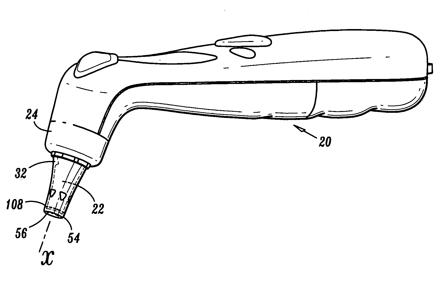
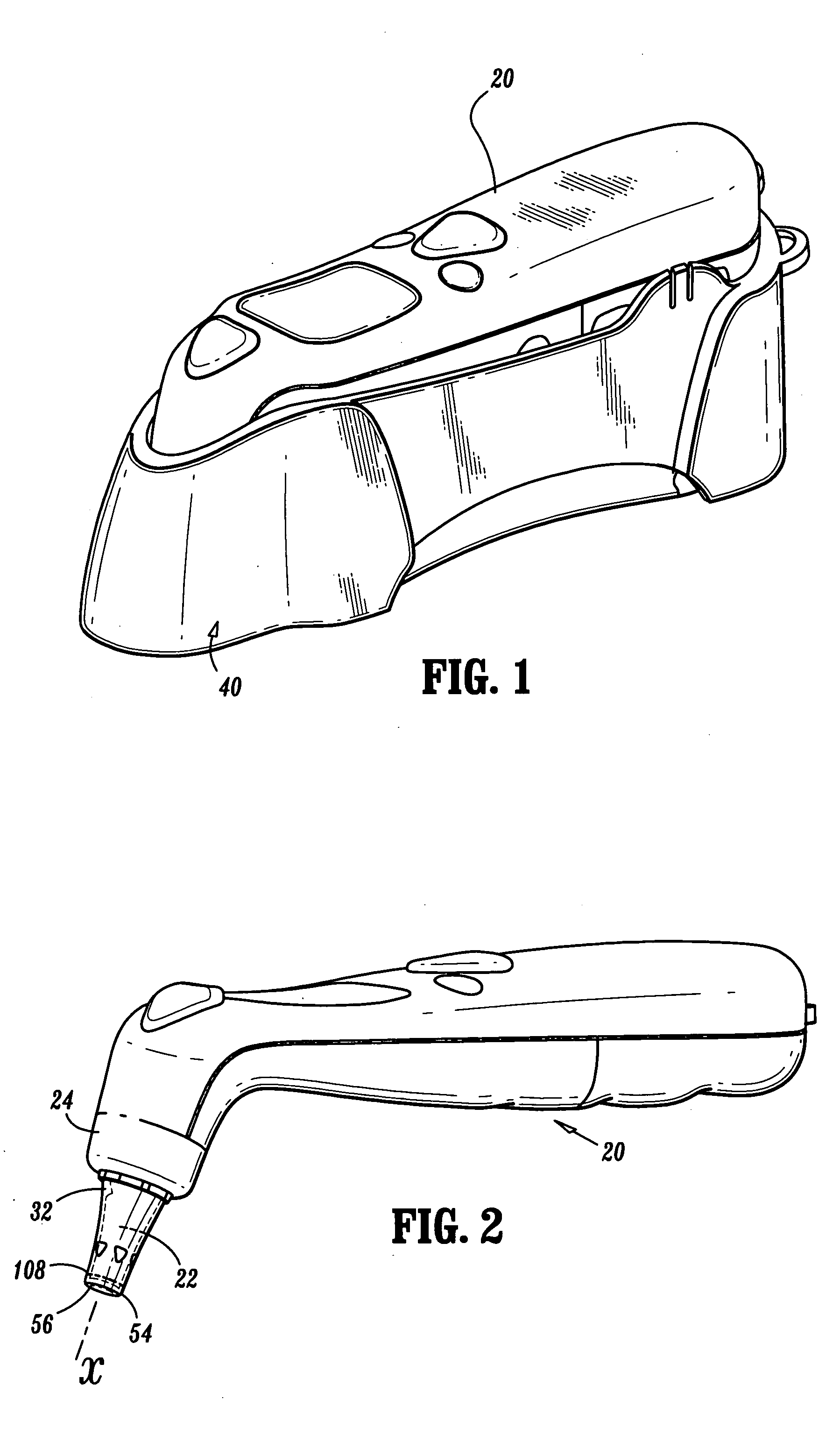
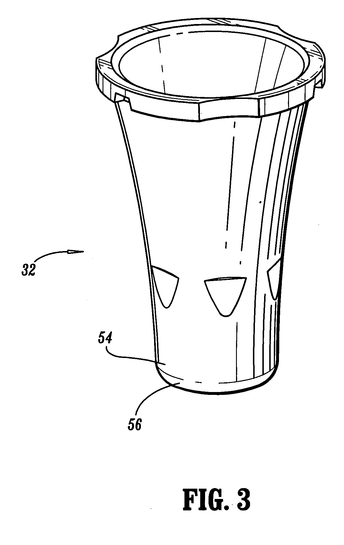
[0040] The exemplary embodiments of the tympanic thermometer and methods of use disclosed are discussed in terms of medical thermometers for measuring body temperature, and more particularly, in terms of a tympanic thermometer that includes a sensor having a nozzle disposed therewith that improves accuracy of temperature measurement. It is envisioned that the present disclosure finds application for the prevention, diagnosis and treatment of diseases, body ailments, etc. of a subject. It is further envisioned that the principles relating to the tympanic thermometer disclosed include proper removal of a used probe cover via the ejection apparatus and indication to a practitioner whether a new, unused probe is mounted to the tympanic thermometer.

[0041] In the discussion that follows, the term “proximal” will refer to the portion of a structure that is closer to a practitioner, while the term “distal” will refer to the portion that is further from the practitioner. As used herein, the...


PUM

PropertyMeasurementUnit
thicknessaaaaaaaaaa
temperatureaaaaaaaaaa

Abstract

A method for reducing temperature measurement error in a tympanic thermometer. The present disclosure provides a tympanic thermometer including a heat sensing probe defining a longitudinal axis and an outer surface extending from a distal end of the tympanic thermometer. The heat sensing probe includes a thermally insulating sensor housing extending to a distal end thereof. Can-packaged temperature sensing electronics are mounted at the distal portion of the sensor housing. A thermally conductive nozzle is configured to direct heat flux to the temperature sensing electronics in the distal end of the heat sensing probe. The sensor can preferably include a lip extending radially therefrom and contacting the nozzle at at least one contact point to provide heat flux to the sensor can.

Description

CROSS REFERENCE TO RELATED APPLCIATION [0001] The present application is a divisional of patent application Ser. No. 10 / 480,428, filed on Dec. 10, 2003, which is a 371 of PCT / US03 / 11606, filed on Apr. 15, 2003, which claims benefit of U.S. Provisional Patent Application No. 60 / 432,904, filed on Dec. 12, 2002, which are hereby incorporated by reference.BACKGROUND [0002] 1. Technical Field [0003] The present disclosure generally relates to the field of biomedical thermometers, and more particularly, to a tympanic thermometer that includes a sensor having a nozzle disposed therewith that improves accuracy of temperature measurement. [0004] 2. Description of the Related Art [0005] Medical thermometers are typically employed to facilitate the prevention, diagnosis and treatment of diseases, body ailments, etc. for humans and other animals, as is known. Doctors, nurses, parents, care providers, etc. utilize thermometers to measure a subject's body temperature for detecting a fever, monito...

Claims


Application Information

Patent Timeline
Patent Type & Authority Applications(United States)
IPC IPC(8): G01J5/02G01J5/04G01J5/06G01K13/00
CPCG01J5/02G01J5/021G01J5/061G01J5/049G01J5/06G01J5/04G01K13/00A61B5/01
Inventor HARR, JAMES
Owner CARDINAL HEALTH IRELAND UNLTD
Why Eureka
Try Eureka