
Vehicle mounted pedestrian sensor system

Inactive Publication Date: 2005-11-17
KUZNAROWIS MARK E
View PDF7 Cites 20 Cited by
  • Summary
  • Abstract
  • Description
  • Claims
  • Application Information

AI Technical Summary

Benefits of technology

[0015] It is an objective of the present invention to provide a vehicle mounted pedestrian sensor system for protecting pedestrians, passengers, and children by automatically alerting the vehicle operator of their presence.
[0017] It is still another objective of the present invention is to provide a vehicle mounted pedestrian sensor system that is adaptable for railway systems so that train operators can be alerted to the hazard and danger of vehicles or pedestrians that may be on or adjacent to the track intersection or crossing when the train is at least one mile from the potential hazard or danger.
[0019] A still further objective of the present invention is to provide a vehicle mounted pedestrian sensor system that operates in a standby mode when the vehicle is moving to prevent the generation of false warning signals.

Problems solved by technology

A critical limitation is that the alarm buzzer is activated only when the vehicle is backing up, but not when the vehicle is moving forward.
However, given the size of buses, garbage trucks, and construction equipment, and the fact that the forward and sideways visibility is often limited or obstructed due to the location of the drivers seat or cab, the operator may not see pedestrians or individuals standing or moving in front of the vehicle even when the vehicle is moving directly forward.
Nonetheless, safety arm doesn't sense anyone's movement or motion about the bus and is under the direct manual control of the bus driver.

Method used


Image

  • Vehicle mounted pedestrian sensor system
  • Vehicle mounted pedestrian sensor system
  • Vehicle mounted pedestrian sensor system

Examples


Embodiment Construction

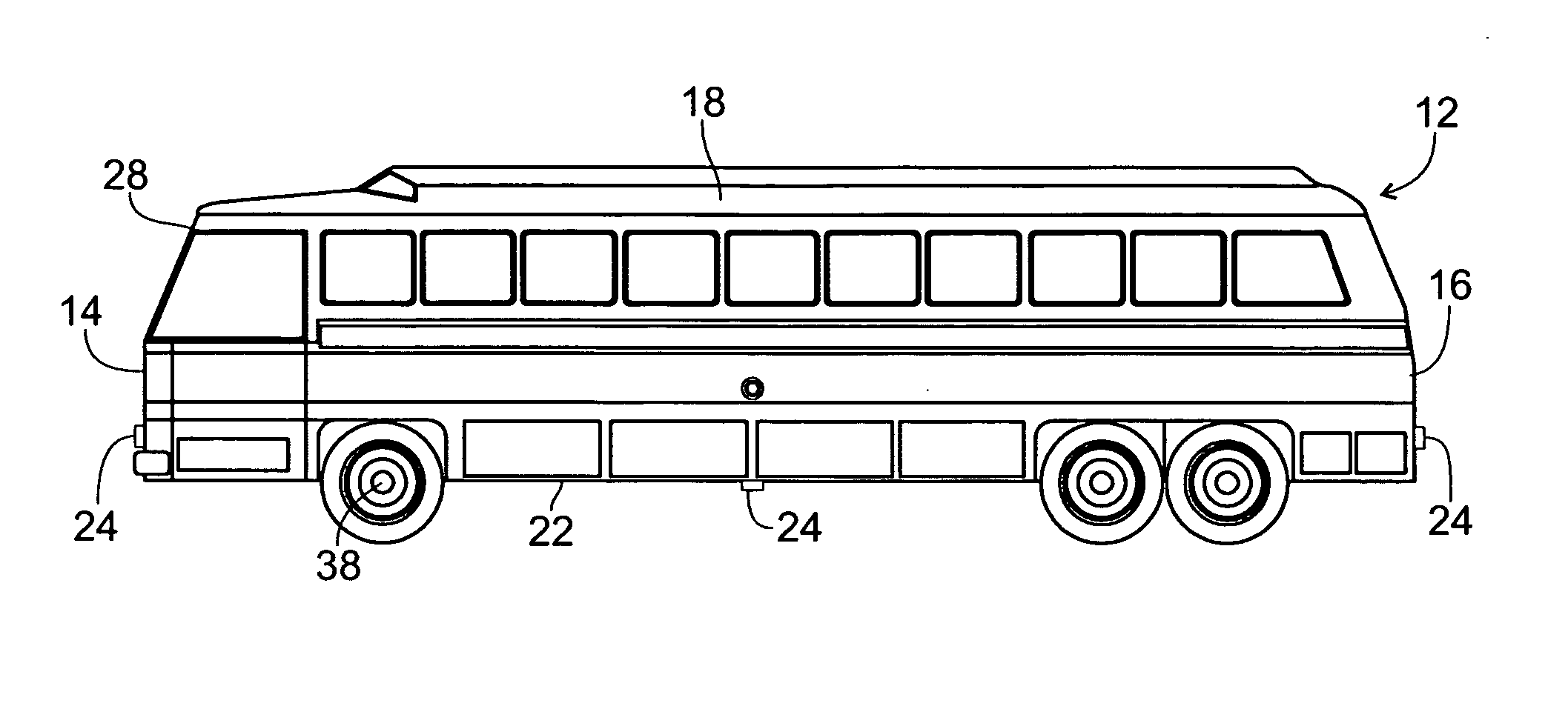
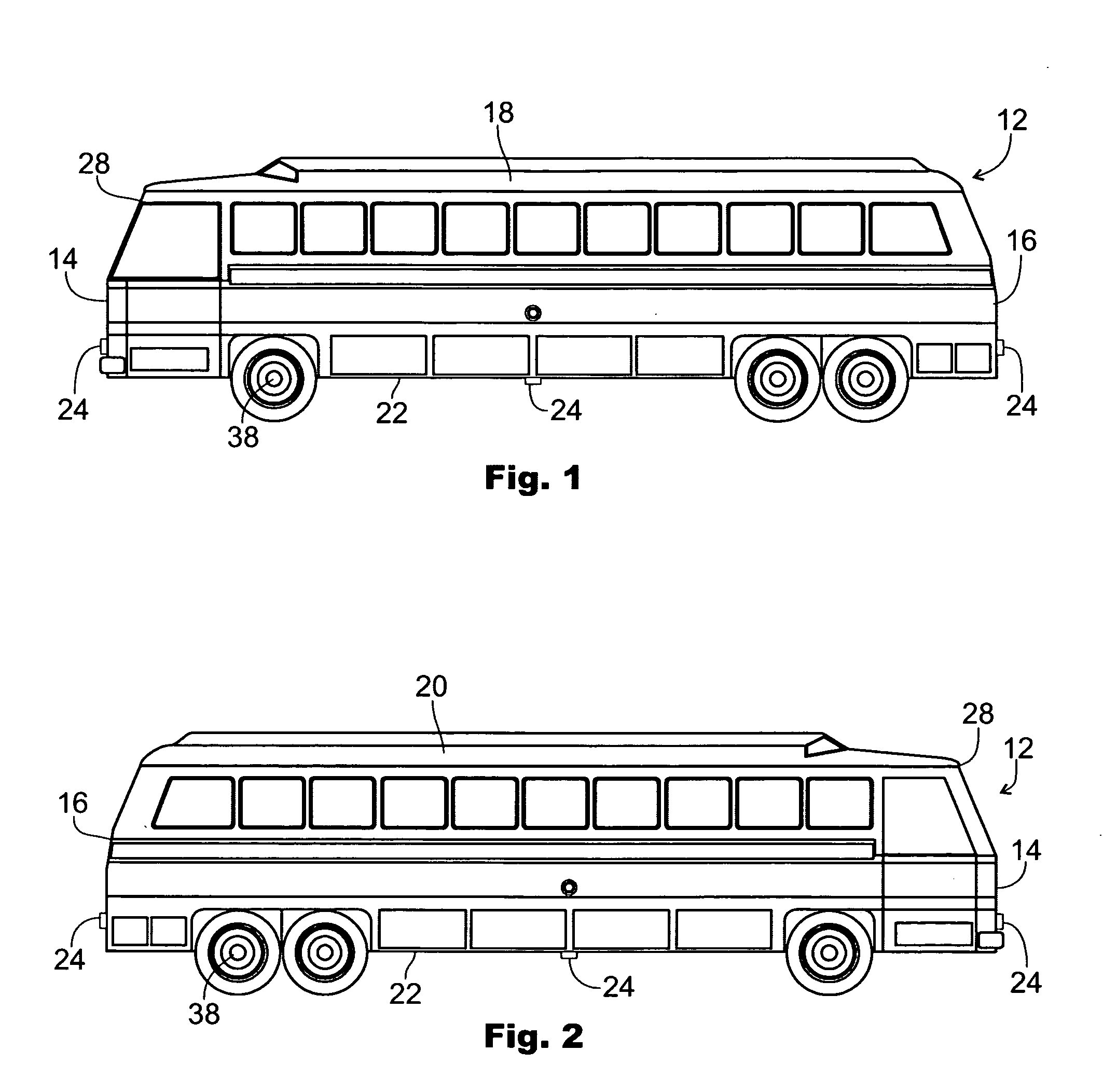
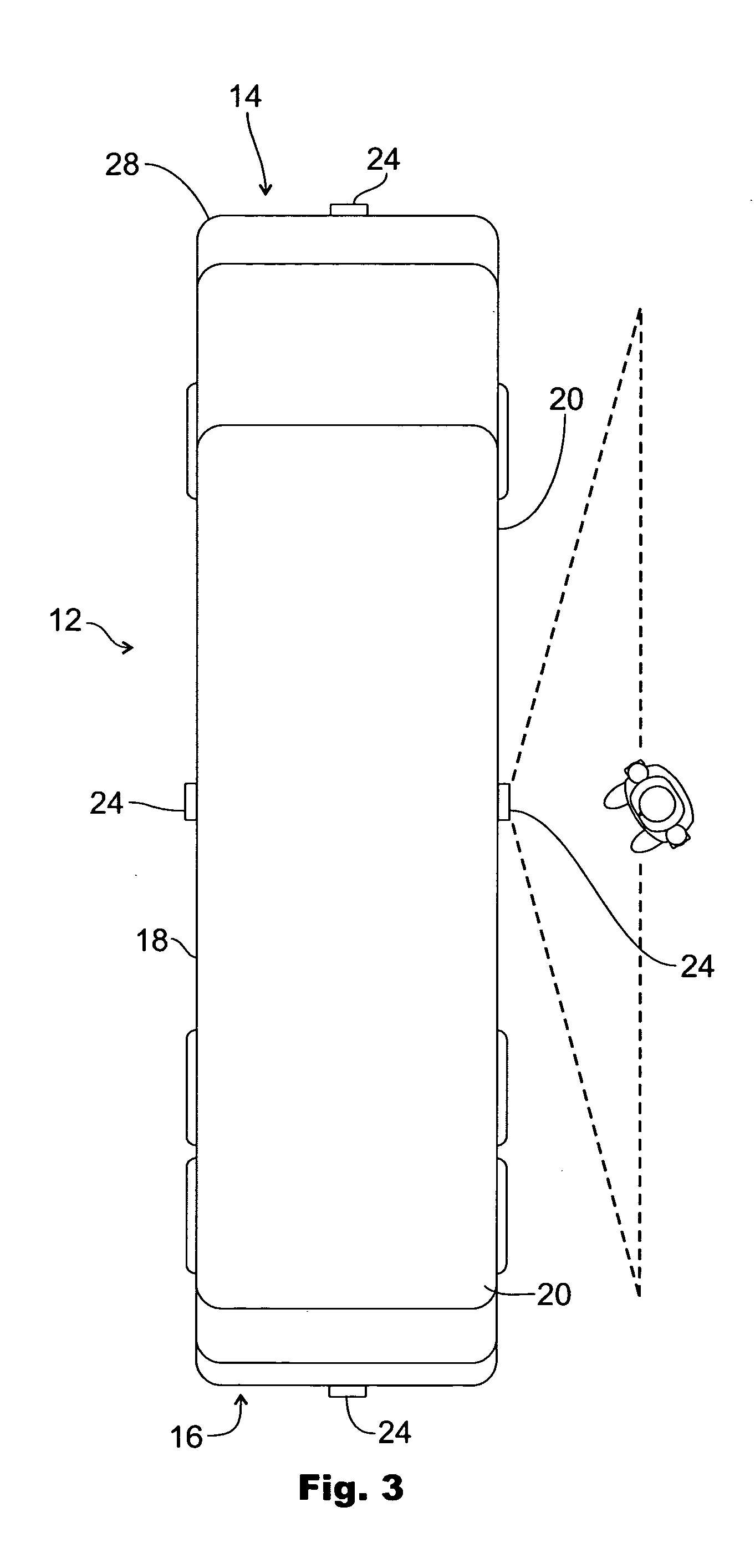
[0033] Illustrated in FIGS. 1-11 are several embodiments for a vehicle mounted sensor system for alerting the vehicle operator of the presence of pedestrians, passengers, and children of the fact that they are moving in front, in back or adjacent both sides of the vehicle and that a dangerous condition exists for all parties. The vehicle can be a commuter bus, construction equipment, moving vans, or garbage trucks; or any large vehicle that has obstructed sight lines or blind spots from the operator's vantage. Thus, the vehicle mounted sensor system is a protection system for both the vehicle operator and individuals moving about the perimeter or vicinity of the vehicle in so far as the individuals are protected from being injured by the vehicle sensor system, and the liability for the vehicle operator and owner is lessened by employing this safety system.

[0034] As shown in FIGS. 1-8, a preferred embodiment of the vehicle mounted sensor system 10 is mounted to and integrated with a...


PUM


Abstract

A vehicle mounted sensor system for detecting the presence of objects and individuals adjacent a vehicle such as a commuter bus includes at least four motion detectors mounted to the front, back and both sides of the vehicle, an electrical control box for receiving and interpreting signals generated by the motion detectors, and a display and control panel having indicator lamps that light in response to one or more of motion detectors being triggered by the presence of an individual within the preset detection range. The control panel also includes a tone or alarm that will also sound in response to the detection of the presence of an individual. An integral sensing switch is interconnected to the control box and either the transmission, the drive shaft or a wheel hub for detecting when the vehicle comes to a stop so that the sensor system can be immediately activated; and when the vehicle resumes motion, the sensor system goes to a standby mode until the integral sensing switch detects the next stoppage of the vehicle and the system is activated.

Description

FIELD OF THE INVENTION [0001] The present invention pertains to motion sensing and detection devices, and more particularly pertains to a motion sensing system that immediately alerts the operator of a motorized vehicle of the presence of pedestrians within a predetermined area about the motorized vehicle. BACKGROUND OF THE INVENTION [0002] Systems and devices to sense and detect the motion, movement or presence of objects and individuals are widespread throughout society. The primary purpose of such sensing and detecting devices is for providing safety to the users and monitors of the devices and systems in so far as they alerted or warned of presence of interlopers or intruders. Two of the most common sensing and detecting devices and systems are the integrated light and motion detectors utilized on residential, commercial and industrial dwellings and sites, and the photoelectric eye found in doorways and entranceways or all manner of buildings and structures. In both cases it is ...

Claims


Application Information

Patent Timeline
IPC IPC(8): B60Q1/00B61L23/00G08G1/16
CPCB61L23/041G08G1/16B61L29/30G08G1/166
Inventor KUZNAROWIS, MARK E.
Owner KUZNAROWIS MARK E
Learn More