
Detachable tube assembly

a tube assembly and detachable technology, applied in the direction of couplings, mechanical equipment, transportation and packaging, etc., can solve the problems of affecting the maintenance of the tube, the user cannot apply the spray to a small area, and the application of some applications is difficul

Inactive Publication Date: 2005-11-17
SC JOHNSON & SON INC
View PDF9 Cites 88 Cited by
  • Summary
  • Abstract
  • Description
  • Claims
  • Application Information

AI Technical Summary

Benefits of technology

[0011] The present invention provides a detachable tube assembly. It has a first tube having at least one of a radial aperture and a radial projection, and a second tube capable of telescoping into an end of the first tube. The second tube has at least one of a radial aperture and a radial projection along a portion of the second tube that is capable of telescoping into said end of the first tube such that a radial projection along one of the tubes can extend into a radial aperture along the other of the tubes. This can lock the two tubes together, in a releasable manner.
[0012] There is also a rod extendable along (preferably through) the second tube, the rod having a radial flexible barb adjacent a distal end of the rod. The flexible barb is sized and dimensioned to pass through the telescopable portion of the second tube while being flexed radially inwardly by the second tube, and then flex radially outwardly when the barb has passed through that telescopable portion, such that a portion (e.g. an end) of the second tube adjacent the telescopable portion thereof can limit return movement of the barb back through the second tube. There is also a guide linked to the rod to move therewith, which extends radially outwardly there from.
[0013] In a preferred form the second tube has a narrowed portion forming at least a part of its telescopable portion, the guide having a greater width than an inner diameter of the narrowed portion of the second tube. This prevents the rod from simply passing out the bottom of the second tube once the rod has been inserted in the top of the second tube.
[0016] The present invention allows pre-assembly (e.g. at the factory) of one of the tubes and the movable rod. A consumer can then, in a highly conceptual manner, be instructed as to how to assemble that subassembly with further such subassemblies. Hence, the device is easier for a consumer to construct. Nevertheless, it is inexpensive to produce, easy to manufacture, and secure in its connection.

Problems solved by technology

This will present problems for some applications.
Consequently, a user cannot apply the spray to a small, localized area such as a window sill, an area under a bush or other plant, or the like, unless the can (and therefore the user's hand) can be within inches of the target area.
It could be somewhat difficult to disassemble the tubes for maintenance and / or other reasons (such as more compact storage between uses).
In such cases, it is the consumer that will typically have to assemble the device.
Where the assembly instructions are complex, it may take the consumer extra time to assemble the device, and in some cases the consumer may become frustrated before assembly is completed.

Method used


Image

  • Detachable tube assembly
  • Detachable tube assembly
  • Detachable tube assembly

Examples


Embodiment Construction

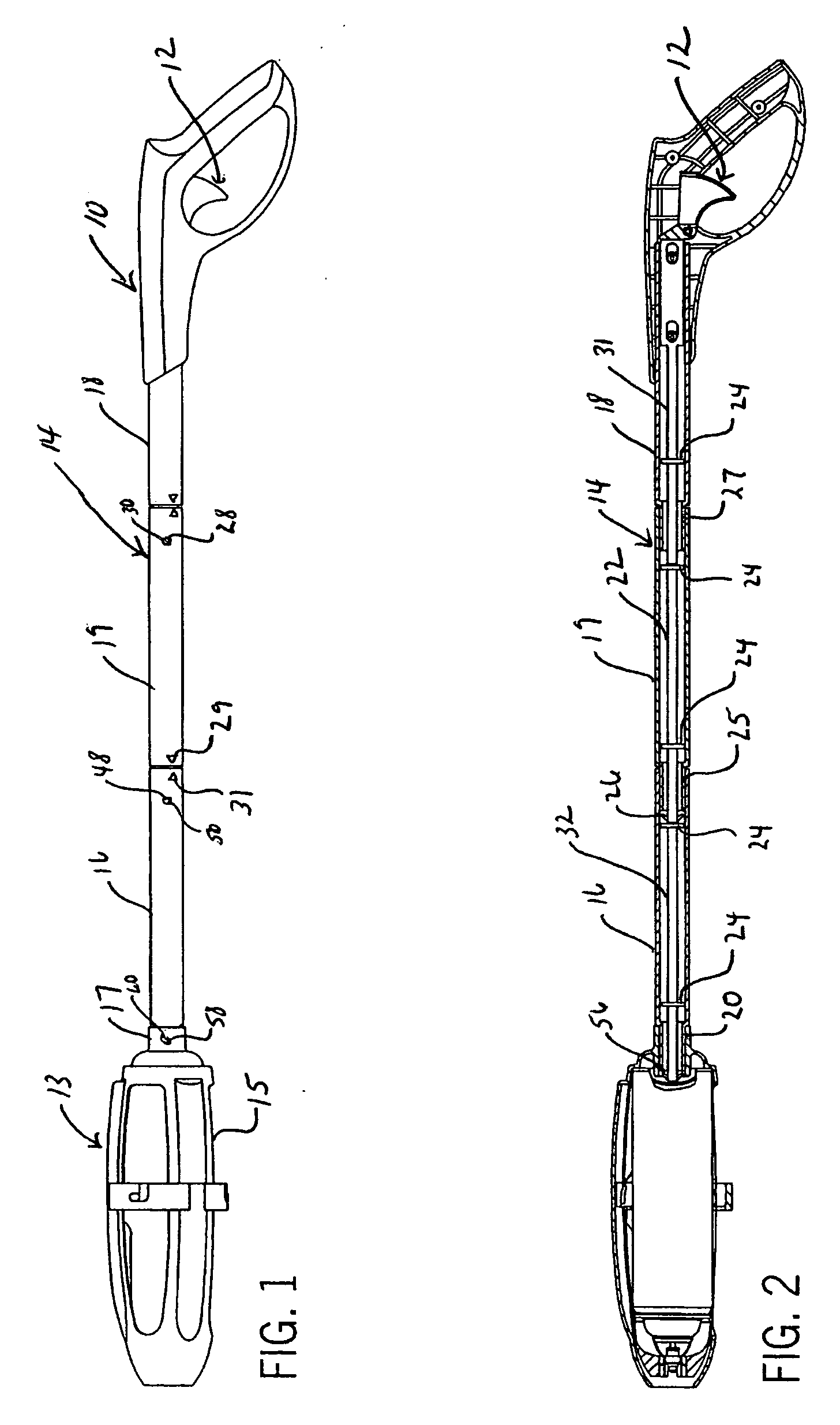
[0025] Referring first to FIG. 1, a sprayer device is shown including a handle assembly (generally 10) for attachment to a canister assembly 13. There is a canister housing 15 for receiving an aerosol can containing a pesticide, insecticide, agricultural chemical, or other chemical to be sprayed. The housing 15 includes a connecting portion 17 which is tubular in shape, and which is detachably connectable to the handle assembly 10. As described below, the handle assembly can include a plurality of tubes 16,18, and 19.

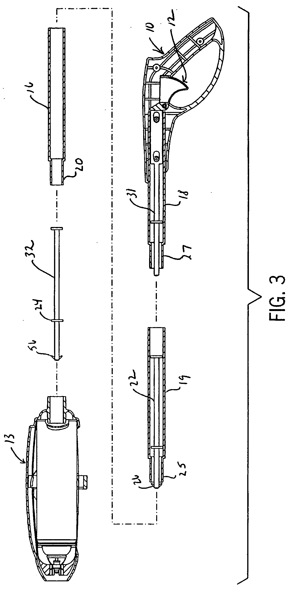
[0026] Referring still to FIG. 1 and now also to FIGS. 2 and 3, a trigger assembly 12 is coupled to an actuator rod formed of multiple segments such as 31, 22, and 32. Rod portion 31 is coupled to the trigger assembly 12 and at the opposing end is sized and dimensioned to contact the next rod 22. Along the length of the rod 22 are positioned one or more disks 24, each having a diameter sized and dimensioned to fit within the tubular segment 19 and to axially align the ...


PUM


Abstract

Detachable tube assemblies, such as those useful in remote spraying devices, are disclosed. Tube segments are interconnected using radial extensions interfit with alignable radial holes on tubes to be coupled together. An actuator rod is provided with flexible barbs and a disk guide. The rod can be used to remotely actuate a spray.

Description

CROSS REFERENCE TO RELATED APPLICATIONS [0001] Not applicable STATEMENT REGARDING FEDERALLY SPONSORED RESEARCH / DEVELOPMENT [0002] Not applicable BACKGROUND OF THE INVENTION [0003] The invention relates to a device for detachably coupling tubes together, and more particularly for detachably coupling tubes for use as part of a handle and actuator system for a remote spray assembly. [0004] Aerosol cans and similar pressurized spray canisters are most frequently actuated by a user directly pressing a button or other structure that activates the can's valve. Typically, this means that the user must directly hold the canister in his or her hand, and the surface to be sprayed must be no further away than can be reached by the spray pattern of the canister. [0005] This will present problems for some applications. For example, except for some specialty sprays designed to project a narrow stream a long distance (such as certain conventional wasp sprayers), most common aerosol sprays tend to f...

Claims


Application Information

Patent Timeline
IPC IPC(8): B05B15/68B65D83/16F16L37/098
CPCF16L37/098B65D83/203
Inventor WESTPHAL, NATHAN R.MINEAU, STEVEN B.
Owner SC JOHNSON & SON INC
Learn More