Automatic visual recognition of biological particles

Inactive Publication Date: 2005-11-10
PERONA PIETRO +2
View PDF2 Cites 115 Cited by
  • Summary
  • Abstract
  • Description
  • Claims
  • Application Information

AI Technical Summary

Benefits of technology

[0020] The classification stage also extracts feature vectors from the detected parts of the image. These feature vectors are used in the classification process. In addition, the invention applies non-linearities to each feature vector that serves to significantly reduce the error rate during classification.

Problems solved by technology

In all these applications, detection and classification are difficult, because of the poor resolution and maybe strong variability of objects of interest, and because the background can also be very noisy and highly variable.
When an allergen is absorbed into the body of an allergic person, the person's immune system views the allergen as an invader and a chain of abnormal reactions begins.
The effects of this response are runny nose, watery eyes, itching and sneezing.
People with these symptoms are unable to work and even to sleep.
This method is slow, expensive, and inaccurate.
First of all: the response time is inadequate for many applications.
The results of such analysis are therefore sometimes available one week after the fact, rendering them useless for preparations of medical response in hospitals.
Second, the analysis of one weekly tape takes up to 8 hours of work by a skilled professional, thus, the yearly cost of measuring pollen contents in the air at one location could approach $30,000, too expensive for many institutions and too expensive to allow fine spatial sampling of air pollen contents.
The most important problem with the use of the above-described prior art is that the reliance on humans produces inaccurate measurements.
Such inaccuracies result from two primary reasons: first, the process is tedious and it is well documented that the attention of a human operator tends to flag after 30 minutes on a demanding repetitive job; second, in order to accomplish the task at all, human operators sample coarsely the collected tapes.
Measurements are thus accurate for high pollen counts, but inaccurate for low pollen counts, and even more inaccurate when estimating the concentration of pollen grains over time.
Moreover, it is difficult to provide accurate pollen levels for areas not near to a counting station and so the actual counts are useless for most of the physicians.
The manual collection and analysis is not adequate because it is too slow, too expensive, not precise and not able to cover all of the territory.
However, microscopic analysis, if manually performed, is intrinsically not precise, time consuming and expensive.
Further, there is no standardization in the process of taking a volume of fluid, there is no reliability of the result because the experts may have a different training and experience, and the work may be annoying because it is repetitive and difficult.
Such difficulty results from the strong similarity among some categories of particles and in the variability existing among corpuscles belonging to the same family.
Moreover, this process is slow and expensive for hospitals.
In view of the above, the manual analysis of urine is not efficient in terms of precision, cost and time, and because the automatic recognition can be improved.
Other systems using different techniques, such as analysis of particle refraction when these particles are hit by a laser beam, have also drawbacks because of their suboptimal performance and the difficulty to verify analysis outcomes.

Method used


Image

  • Automatic visual recognition of biological particles
  • Automatic visual recognition of biological particles
  • Automatic visual recognition of biological particles

Examples


Embodiment Construction

[0086] In the following description, reference is made to the accompanying drawings which form a part hereof, and which is shown, by way of illustration, several embodiments of the present invention. It is understood that other embodiments may be utilized and structural changes may be made without departing from the scope of the present invention.

Overview

[0087] One or more embodiments of the invention provide a system for automatic recognition of particle categories. Furthermore, the system provides a general approach to enable work with several kinds of corpuscles which are found in microscopic analysis. In this way, it is easy to add new classes to the already considered set and, no new customized reprogramming is required.

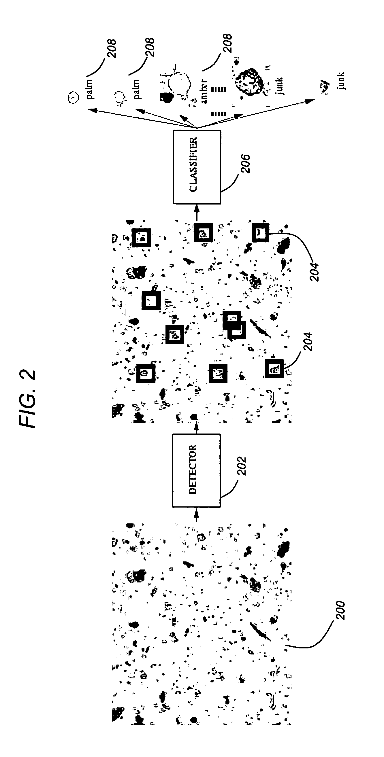
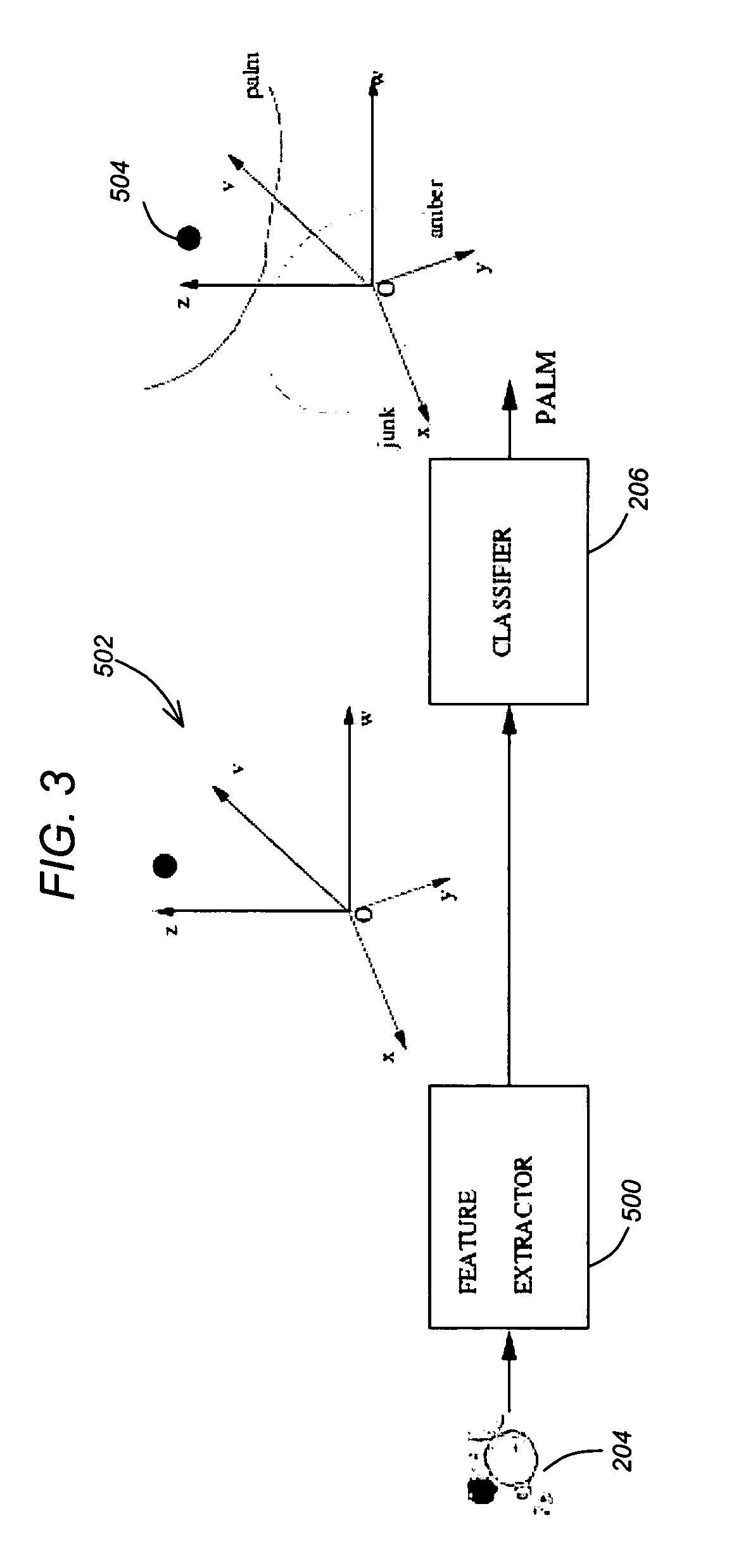
[0088] Generally, input images of a system have resolution of nearly 1024×1024 pixels, while the objects of interest have square bounding boxes with sides between 30 and 200 pixels. The average side is around 60 pixels. Accordingly, the system has to handle ...


PUM


Abstract

A method and system provide the ability to automatically recognize biological particles. An image of biological particles (e.g., airborne pollen or urine) is obtained. One or more parts of the image are detected as containing one or more particles of interest. Feature vector(s) are extracted from each detected part of the image. Non-linearities are applied to each feature vector. Each part of the image is then classified into a category of biological particle based on the one or more feature vectors for each part of the image.

Description

CROSS-REFERENCE TO RELATED APPLICATIONS [0001] This application claims the benefit under 35 U.S.C. Section 119(e) of the following co-pending and commonly-assigned U.S. provisional patent application(s), which is / are incorporated by reference herein: [0002] Provisional Application Ser. No. 60 / 568,575, filed on May 5, 2004, by Pietro Perona, entitled “AUTOMATIC VISUAL RECOGNITION OF BIOLOGICAL PARTICLES,” attorneys' docket number 176.26-US-P1 / CIT-4097-P.STATEMENT REGARDING FEDERALLY SPONSORED RESEARCH AND DEVELOPMENT [0003] The invention was made with Government support under Grant No. ERC: EEC-9402726 awarded by the National Science Foundation. The Government has certain rights in this invention.BACKGROUND OF THE INVENTION [0004] (Note: This application references a number of different publications as indicated throughout the specification by one or more reference numbers within brackets, e.g., [x]. A list of these different publications ordered according to these reference numbers...

Claims


Application Information

Patent Timeline
IPC IPC(8): G01N33/48G01N33/50G06F19/00G06K9/00G06K9/52G06K9/62
CPCG06K9/00134G06K9/6278G06K9/522G06V20/693G06V10/431G06F18/24155
Inventor PERONA, PIETRORANZATO, MARC'AURELIOFLAGAN, RICHARD C.
Owner PERONA PIETRO
Why Eureka
Try Eureka