
Interface test system

Active Publication Date: 2005-11-10
OSTMEIER HUBERT
View PDF10 Cites 35 Cited by
  • Summary
  • Abstract
  • Description
  • Claims
  • Application Information

AI Technical Summary

Benefits of technology

[0023] Such test plug emphasis is preferable, as building the test characteristics in the test plug simplifies the block (lower cost and complexity) and allows the test characteristics to become portable. Further, the present invention provides an automatic operating sequence.
[0043] Yet another object of the present invention is to provide a system incorporating automatic operation (as opposed to manual), which avoids costly error. Pre-configured, standard pole designations reduce time during onsite testing.

Problems solved by technology

In the early days of electricity, spectacular failures were commonplace.
These devices typically were complex electromechanical assemblies.
Electrical parts eroded, burned, and failed in use.
Known metering and relay devices were no longer able to accommodate these currents directly.
However, the current transformer solution is limited.
In such a configuration, the current transformer fails catastrophically as a result of over-excitation, magnetic core saturation, over temperature, core interleaf, and winding insulation breakdown.
This system has been rendered unsafe for the use in nuclear power stations since the 1970s but has been in use in various places up to today nevertheless.
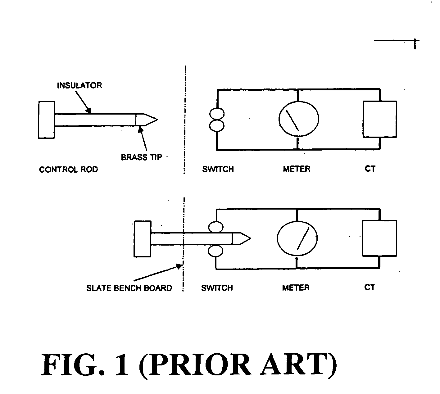
FT switches incorporate disadvantages, including that the contacts have to be opened individually, the user needs to know the whole setup of the system; manual opening and closing makes way for human error that can be dangerous; manual opening puts the user at risk of electrical shock; the used material (stud-welded stainless steel) has high internal resistance of 200-300 Milliohms and reaches temperatures of more than 70 degrees Celsius; and all operations (elimination of CTs and PTs, qualified injection) have to be performed by highly trained professionals.
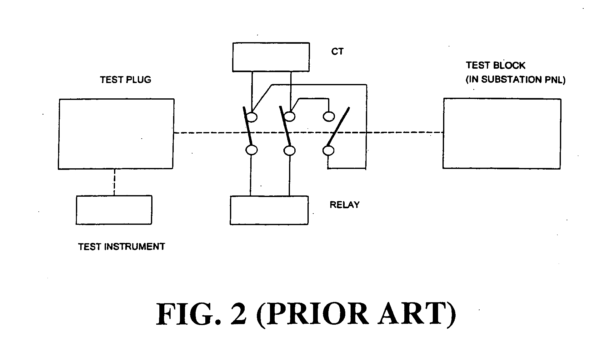
A disadvantage of the block focus is that it places the test characteristics (higher cost and complexity) in the device installed in the substation panel.
This momentary polarity reversal is a serious design flaw that may cause damage to any connected device with a grounded (earthed) power supply input terminal.

Method used


Image

  • Interface test system
  • Interface test system
  • Interface test system

Examples


Embodiment Construction

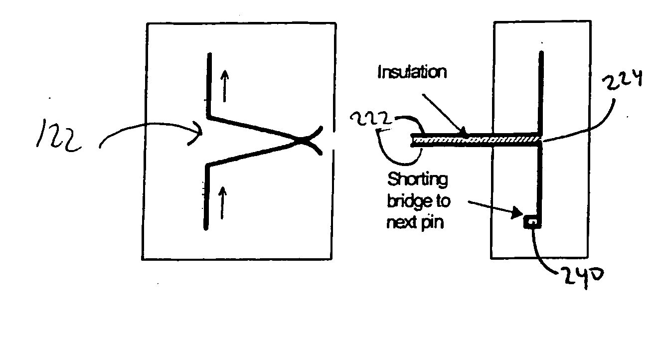
[0063] The present invention is an innovative approach to test switch technology. The invention provides safe access to control, protection, and automation devices in a secondary circuit. In accordance with a preferred embodiment, the present invention generally comprises a test block and a test plug for testing circuits connected to an electrical panel.

[0064] The test block assembly is preferably simple, facilitating entry into a circuit or the closure of a circuit. The test block assembly in accordance with a preferred embodiment of the present invention comprises a contact spring pair. The spring pair is preferably bent into a specified shape at its knee so that the spring pair contact forming a contact point. In addition, the bent shape of the spring pair provides extra strength to the spring pair and prevents the spring pair from breaking or becoming damages when being utilized.

[0065] The test block can be mounted in an electrical panel for long time periods, and since it onl...


PUM


Abstract

The present invention relates to an interface test system. In one embodiment, an interface test device for testing a circuit connected comprises a block having a first aperture and a plug having a finger to insert into the first aperture. The finger can have insulation disposed between pins to isolate the pins, maintain correct polarity for the circuit, and open and connect to a circuit substantially simultaneously. An interface testing method for a circuit can comprise inserting a finger of a test module into a first aperture of a block module, opening the circuit with the finger, and connecting the finger to the circuit. The opening and connecting to the circuit occur substantially simultaneously to achieve a make-before-break sequence. Other embodiments are also claimed and described.

Description

BENEFITS CLAIM [0001] This application claims the benefit of Provisional Application No. 60 / 567,958, filed 4 May 2004.BACKGROUND OF THE INVENTION [0002] 1. Field of the Invention [0003] The present invention relates generally to an interface test system, and relates more specifically to a test block and test plug for relay and meter testing. [0004] 2. Description of Related Art [0005] Test blocks, test plugs, test probes, and related devices are most often found in direct association with current transformers, potential transformers, metering apparatus, and protective relay systems. The supply of electricity must be continuous and uninterrupted by breakdown. In the early days of electricity, spectacular failures were commonplace. Accurate revenue metering devices, protective relays, and circuit interrupting devices were thus developed. These devices typically were complex electromechanical assemblies. Mechanical parts needed to be lubricated, adjusted, and aligned. Electrical parts ...

Claims


Application Information

Patent Timeline
IPC IPC(8): G01R1/04H01R9/24H01R13/46H01R13/52H01R13/642H01R13/71
CPCG01R1/0416H01R9/2433H01R13/465H01R13/642H01R2201/20H01R24/20H01R24/28H01R2101/00H01R13/71
Inventor OSTMEIER, HUBERT
Owner OSTMEIER HUBERT
Learn More