
Cabinet for computer devices with air distribution device

a computer device and air distribution technology, applied in the direction of electrical apparatus casings/cabinets/drawers, heating types, separation processes, etc., can solve the problems of large heat accumulation, large heat accumulation in existing cabinets, and major contributing factors to the failure of computer components within the cabinet. , to achieve the effect of reducing the temperature gradient within the cabinet, reducing the amount of heat generated by the devices and remaining within the internal chamber of the cavity

Inactive Publication Date: 2005-11-10
POWER OF 4 LLC
View PDF99 Cites 46 Cited by
  • Summary
  • Abstract
  • Description
  • Claims
  • Application Information

AI Technical Summary

Benefits of technology

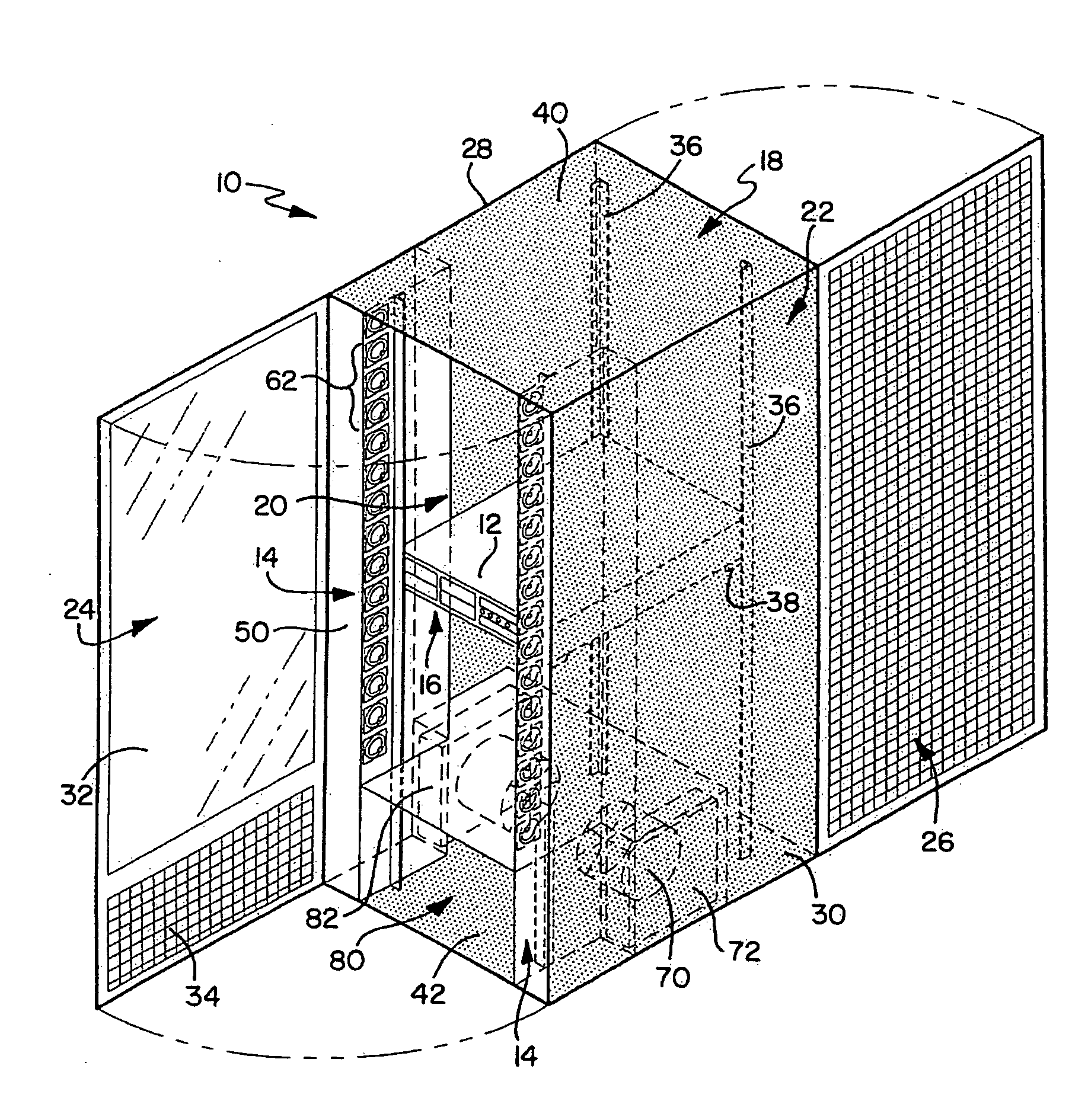
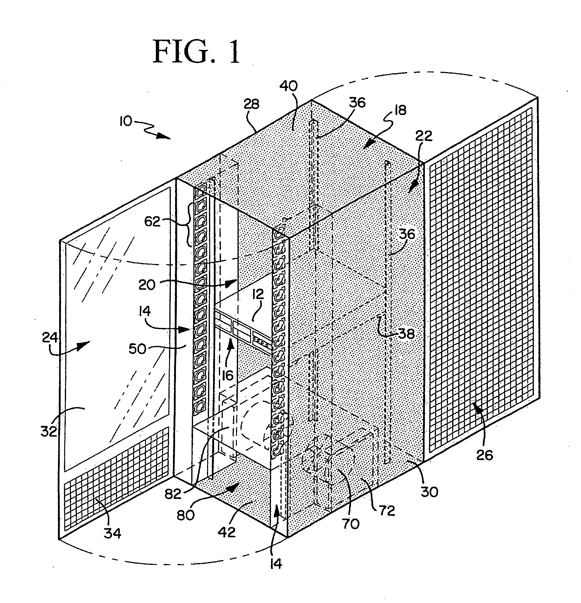
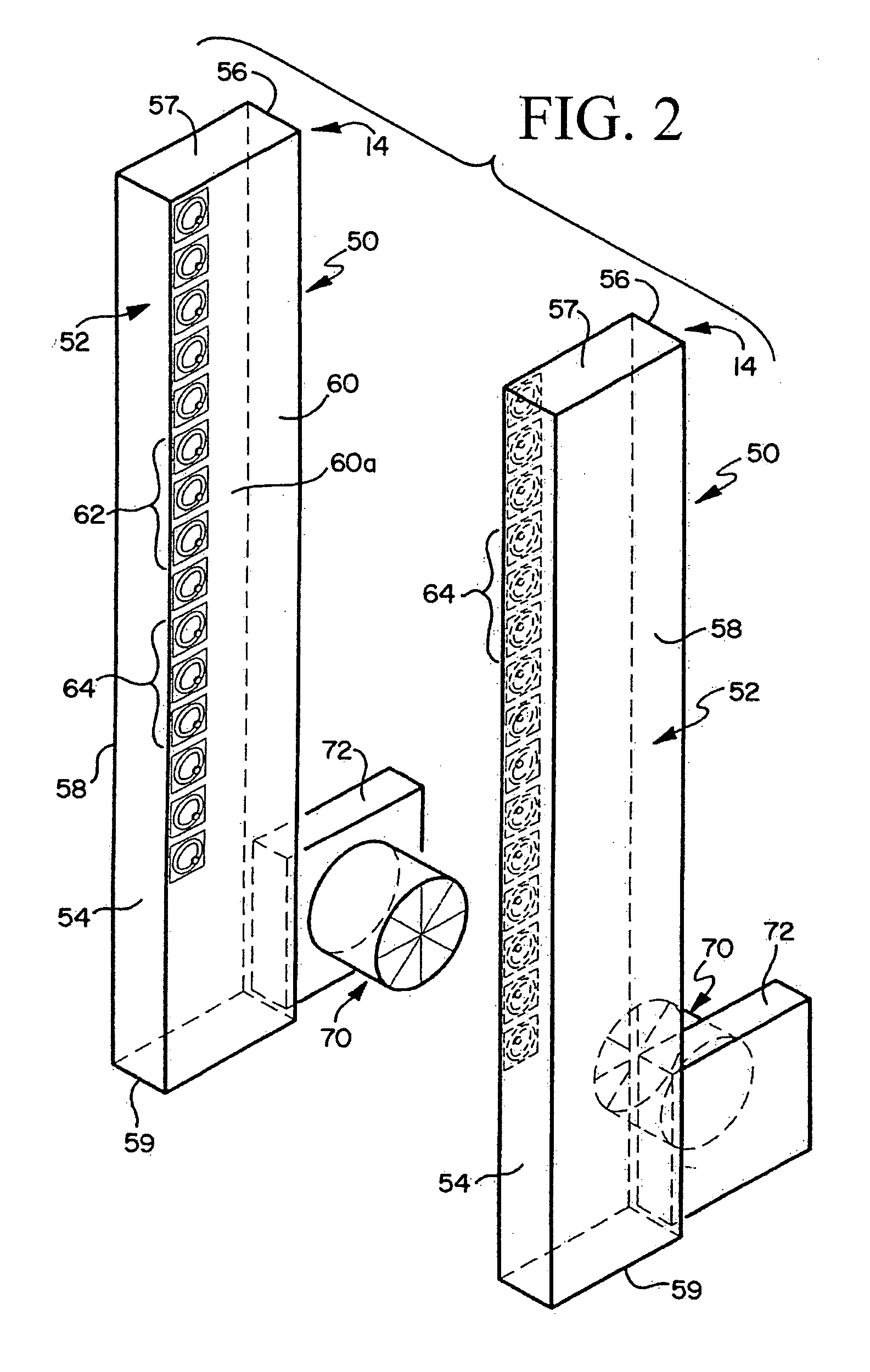
"The present invention is a cabinet for housing computer devices or servers. The cabinet has an internal chamber with at least one air distribution device that draws in and selectively distributes ambient room air to a frontal region of the computer devices. The air distribution device includes an elongated duct, a plurality of discharge ports, an inlet fan, and a plenum. The duct is positioned substantially vertical within the cabinet between the side wall arrangement and the support structure. The discharge ports are adjustable nozzles that can be selectively altered to control the volume and direction of the air flow. The invention reduces the amount of heat that is generated by the devices and that remains within the internal chamber of the cavity, resulting in a reduction of the temperature gradient within the cabinet. The enlarged cabinet has two distinct internal chambers, each with at least one air distribution device."

Problems solved by technology

Existing cabinets suffer from a number of problems including the excessive build-up or accumulation of heat that is generated during operation of the computers.
It is well-recognized that heat is a major contributing factor to the failure of the computer components within the cabinet.
Because a greater amount of heat is found at the upper portion of the cabinet, the computers positioned in the upper portion of the rack experience a greater failure rate than those positioned in the lower portion of the rack.
Although computers in the upper portion of the cabinet tend to fail at a higher rate, the computers in the lower portion of the cabinet can fail, especially when a large amount of heat is present.
However, the cooling devices of these cabinets do not provide a uniform flow of cooling air throughout the cabinet, thereby reducing the effectiveness of the device.
In addition, these cooling devices create number of installation problems due to large dimensions and bulky configurations.
Due its arrangement of fans, this device cannot provide cool air to specific locations within the cabinet and, as a result, does not address the temperature gradient explained above.
In addition, this device has large dimensions which can negatively affect the positioning of the host cabinet and nearby cabinets.
Another cabinet and cooling device marketed by Liebert Corp. and marketed under the RackCooler trade name suffers from similar problems.
Unlike the previous device, the RackCooler is a complex device that includes a cooling coil with a hose for attachment to a cooling unit.
In addition to the limitations presented above, this device is costly and requires additional connections to the cooling unit.
Collectively, these computer cabinets cannot uniformly distribute cool air within the cabinet to address the temperature gradient and, as a result, are not effective at addressing the issues identified above.

Method used


Image

  • Cabinet for computer devices with air distribution device
  • Cabinet for computer devices with air distribution device
  • Cabinet for computer devices with air distribution device

Examples


Embodiment Construction

[0027] While this invention is susceptible of embodiments in many different forms, there is shown in the drawings and will herein be described in detail a preferred embodiment of the invention with the understanding that the present disclosure is to be considered as an exemplification of the principles of the invention and is not intended to limit the broad aspect of the invention to the embodiment illustrated.

[0028] Referring to FIG. 1, a cabinet 10 for housing computer devices or servers 12 is shown. The cabinet 10 has at least one internal air distribution device 14 that is configured to selectively distribute ambient air to a frontal portion 16 of the computer devices 12. In most installations, the cabinet 10 is placed in an air conditioned environment, such as an air conditioned data center, so the ambient air is generally cool air. The frontal portion 16 of the computer device 12 includes the front face and the front portion of the adjacent side walls of the device 12 . Altho...


PUM

PropertyMeasurementUnit
perimeteraaaaaaaaaa
permeableaaaaaaaaaa
heataaaaaaaaaa

Abstract

A cabinet for housing computer devices with an internal air distribution system is disclosed. The cabinet includes an internal chamber defined by a side wall arrangement having at least a front wall. The cabinet includes a support structure for computer devices, wherein the support structure is positioned within the internal chamber of the cabinet. The air distribution device comprises an elongated duct defining a passageway for air distribution. The duct is positioned within the internal chamber and has at least one adjustable air discharge port that is in fluid communication with the passageway. The air distribution device further includes an inlet fan in fluid communication with the passageway. By precisely directing cool air to a frontal portion of the computer devices, the air distribution device reduces the temperature gradients within the cabinet and the quantity of heat that accumulates in the cabinet during operation of the computer devices.

Description

CROSS-REFERENCE TO RELATED APPLICATIONS [0001] This application is a continuation of co-pending U.S. patent application Ser. No. 10 / 756,820, filed Jan. 13, 2004, which application is incorporated herein by reference and made a part hereof.FEDERALLY SPONSORED RESEARCH OR DEVELOPMENT [0002] Not applicable. TECHNICAL FIELD [0003] The present invention relates to a cabinet for an arrangement of computer devices and having an internal air distribution device. More specifically, the present invention relates to a cabinet with an internal air distribution device that selectively delivers ambient room air to an arrangement of computer devices. BACKGROUND OF THE INVENTION [0004] Cabinets for a stack of computer devices are well-known in the computer accessory industry. Conventional cabinets are generally rectangular structures with an internal region that contains a rack for storing and supporting multiple computers. Typically, the rack has a multitude of slots that receive and support the c...

Claims


Application Information

Patent Timeline
Patent Type & Authority Applications(United States)
IPC IPC(8): F24F9/00H05K7/20
CPCH05K7/20736F24F9/00
Inventor BETTRIDGE, JAMES M.FORD, THOMAS K.TUREK, JAMES R.
Owner POWER OF 4 LLC
Learn More