Interface pannel structure

a technology of interface outlets and pannels, which is applied in the direction of electrical apparatus casings/cabinets/drawers, coupling device connections, instruments, etc., can solve the problems of wasting time and labor, limiting the range of interface outlets, etc., to enhance the flexibility of use, enhance the convenience of maintenance or replacement, and keep the outlook of the front frame of the electric machine compact and integrated

Inactive Publication Date: 2005-11-10
CORETRONIC
View PDF4 Cites 13 Cited by
  • Summary
  • Abstract
  • Description
  • Claims
  • Application Information

AI Technical Summary

Benefits of technology

[0005] One object of the present invention is to provide an interface panel structure, using a movable type design matching a fixed seat with a sliding seat to replace the conventional fixing type design disposing an opening in a front frame to enhance convenience for maintaining or replacing an interface panel.
[0006] Another object of the present invention is to provide an interface panel structure, utilizing installments of a fixed seat and movable sliding seat in a housing to allow an interface panel to be hidden in the housing while not being used and to be exposed when it is in use so as to keep the outlook of a front frame of an electric machine compact and integrated.
[0007] Still another object of the present invention is to provide an interface panel structure, allowing the interface panel structure to be used in every kind of electric machine to enhance its use flexibility by integrating the interface panel structure into a module structure.
[0008] For attaining to the objects mentioned above, an interface panel structure according to the present invention is used in an electric machine; it comprises a fixed seat disposed with a holding element and a plurality of sliding rails and a movable sliding seat installed therein. A plurality of fixing holes for accepting the holding element and sliding grooves operated in cooperation with the sliding rails are disposed in the two flank sides of the sliding seat. In addition, a guide rod is installed in the sliding seat for touching off the holding element and then separating it from the fixing hole. When the holding element and the fixing hole are engaged, the sliding seat with interface outlets disposed at the front face thereof is hidden in the fixed seat in the electric machine. And, when the interface outlets need to be used, only the guide rod is operated to touch off the holding element to separate it from the fixing hole so that the sliding seat is allowed to slide down to cause the outlets to be exposed for a user to plug in or pull out cables or wires and to process maintenance conveniently. Besides, there is no need to open holes on the surface of the electric machine by means of the interface panel structure according to the present invention so that the outlook of the electric machine can be prevent from being spoiled.

Problems solved by technology

And, the interface outlets 2 installed in the frame body are also replaced through a complicate detachment procedure so as to cause the variability of the interface outlets to be limited.
If a maintenance or replacement is needed, the detachment wastes time and labor.

Method used


Image

  • Interface pannel structure
  • Interface pannel structure
  • Interface pannel structure

Examples


Embodiment Construction

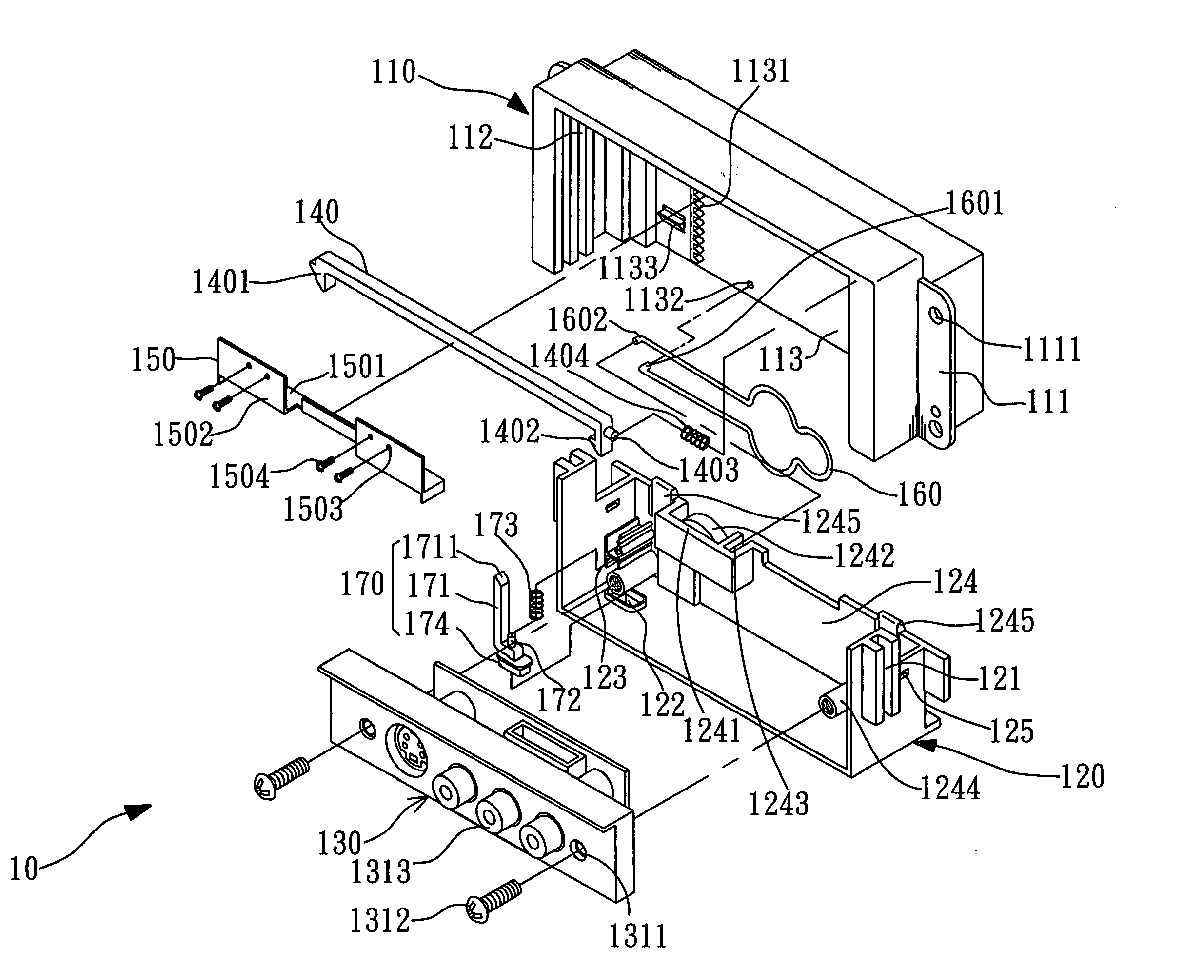
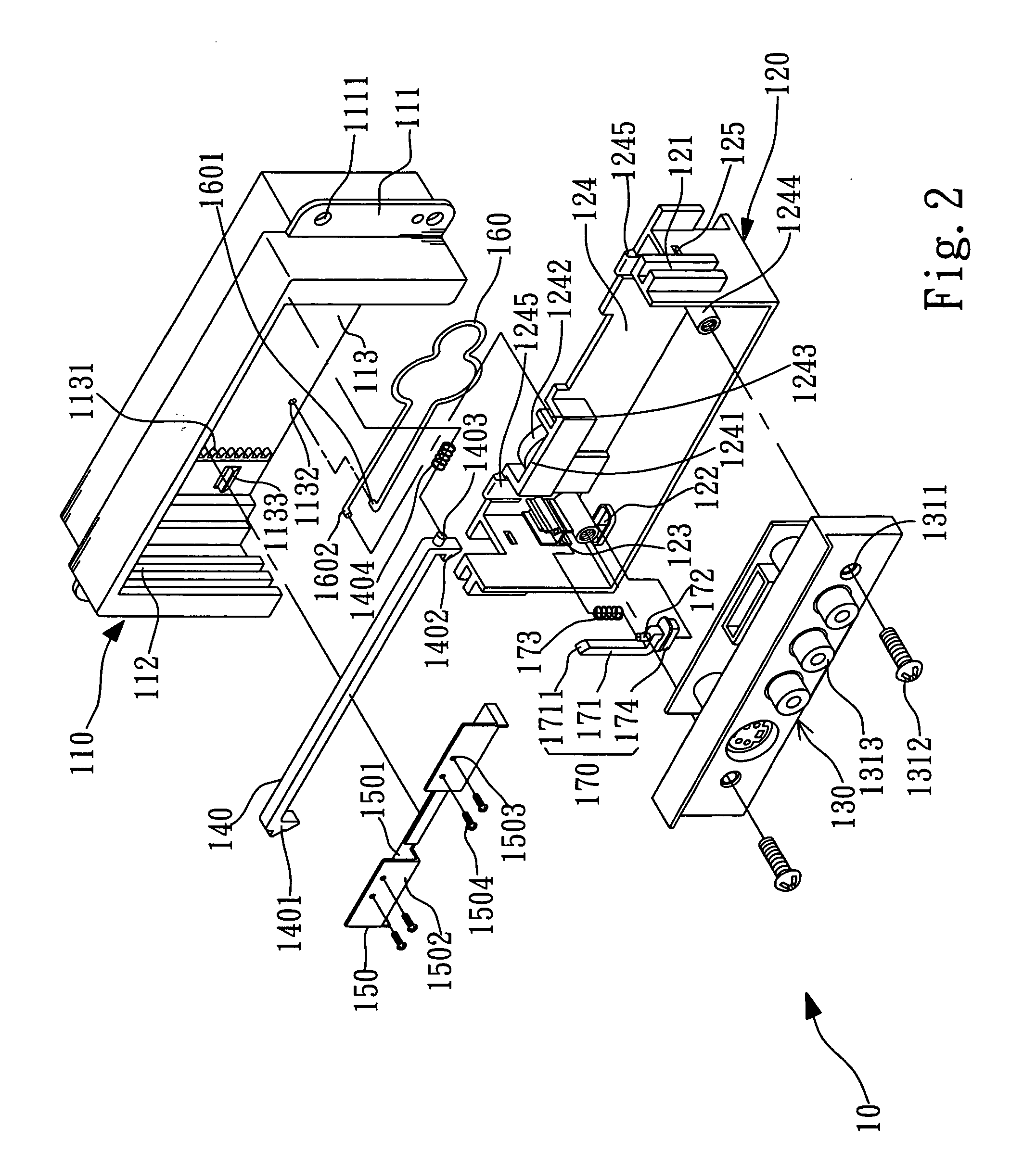
[0016] Please refer to FIGS. 2 and 3. An interface panel structure 10 mainly comprises a fixed seat 110, sliding seat 120 and interface panel 130.

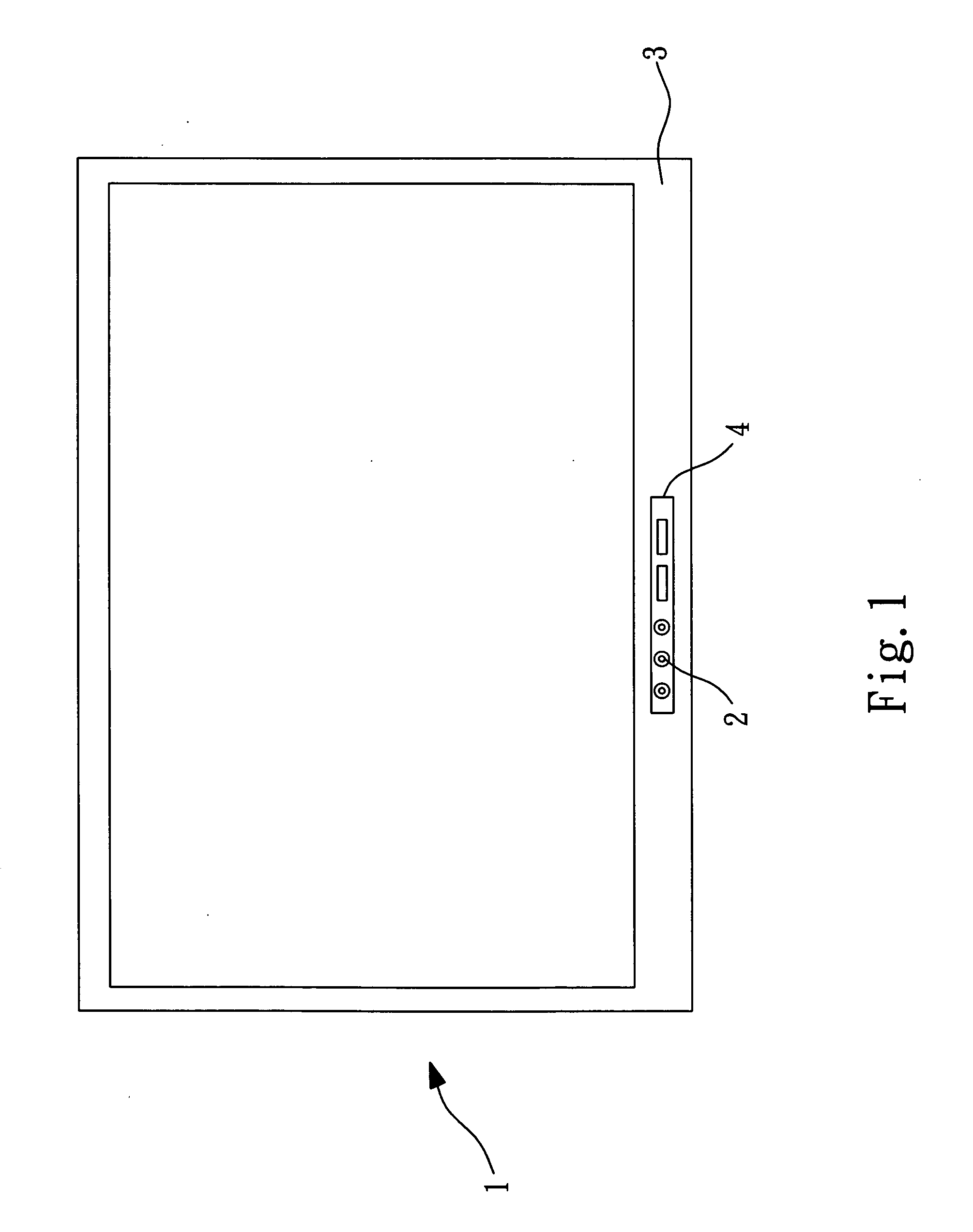
[0017] The fixed seat 110 is a shape hollow structure and a fixing sheet 111 is respectively extended out at each side thereof. A plurality of screw holes 1111 are disposed in the fixing sheet 111 for a plurality of screws (not shown in the figure) to pass through the screw holes 1111 to fix the fixed seat 111 inside of a frame body 5 of an electric machine (not shown in the figure). According to a preferred embodiment of the present invention, the fixed seat 110 is fixed behind the front frame of the frame body; but it can be also installed at one flank side of the frame body. Here, the electric machine can be a liquid crystal display, plasma television set, rear projection television set or anything else. A plurality of sliding rails 112 are disposed at the inside faces of the two flank sides of the fixed seat 110. A longitudinal rack ...


PUM


Abstract

An interface panel structure used in an electric machine; comprises a fixed seat with a fixed seat with a holding element and sliding rails and a movable sliding seat installed therein. Fixing holes for accepting the holding element and sliding grooves operated in cooperation with the sliding rails are disposed in the sliding seat. In addition, a guide rod is installed in the sliding seat for touching off the holding the holding element to separate it from the fixing hole. When the holding element and the fixing hole are engaged, the sliding seat with interface outlets disposed at the front face thereof is hidden in the fixed seat fixed in the electric machine. And, there is no need to open holes on the surface of the electric machine by means of the interface panel structure.

Description

BACKGROUND OF THE INVENTION [0001] 1. Field of the Invention [0002] The present invention relates to an interface panel structure, and more particularly to an interface panel structure capable of being concealed or exposed in an electric machine. [0003] 2. Description of Related Art [0004] Please refer to FIG. 1. Interface outlets 2 are installed in a frame body of a conventional electric machine 1 and an opening 4 is opened at the corresponding position of the outlets 2 on a front frame 3 so as to allow the interface outlets 2 to be exposed for a user to plug in or pull out cables. However, the exposition of the front faces of the interface outlets 2 is easy to spoil the entirety outlook of the machine and the problem of assembly clearance is still existed at the front faces of the interface outlet 2 even if a decoration cover (not shown in the figure) is installed. Besides, a mold needs to remade so as to change the opening opened in the front frame when the numbers of the interfa...

Claims


Application Information

Patent Timeline
Patent Type & Authority Applications(United States)
IPC IPC(8): B65D6/28H04N5/64H05K7/10
CPCH04N5/64H01R2201/18
Inventor TSENG, YUNG CHUANKO, KUAN CHOUYUAN, YI CHENGCHANG, CHEN YU
Owner CORETRONIC
Why Eureka
Try Eureka