
Method of operating a solar cell

a solar cell and solar energy technology, applied in the field of solar cells, can solve the problems of low recombination loss, poor quality of materials, and still present non-desired recombination mechanisms, and achieve the effect of reducing stress

Inactive Publication Date: 2005-11-10
IMPERIAL INNOVATIONS LTD
View PDF29 Cites 93 Cited by
  • Summary
  • Abstract
  • Description
  • Claims
  • Application Information

AI Technical Summary

Benefits of technology

The present invention provides a method for operating a solar cell with a strain balanced multiple quantum well stack containing greater than thirty quantum wells. The method involves receiving incident radiation with a high intensity, absorbing photons both within and outside the quantum well stack, and recombining electrons and holes to generate electrical energy. The efficiency of the solar cell is enhanced by the use of a Bragg stack or multiple-layer reflector beneath the quantum well stack. The method also includes the use of a further absorption region with a band gap matched the re-radiated photons to absorb them with a high probability. The quantum well stacks can be formed using various methods, such as layers of GaAs or InyGaAs layers. The invention provides a more efficient solar cell design with improved radiative recombination and reduced Shockley recombination.

Problems solved by technology

However, unavoidable misfit and threading dislocations from the virtual substrate ensure non-desired recombination mechanism are still present.
Quaternary III-V compounds could fulfil the absorption edge condition while remaining lattice matched to GaAs, but the material is of such poor quality that achieving low recombination loses is at present unlikely.
Strained GaAs / InGaAs quantum wells can achieve band-gaps that approach the desired band-gap, but the strain limits the number of quantum wells that can be incorporated without introducing dislocations and, below or above that limit, the current gain compared to a GaAs cell is insufficient to overcome the voltage loss.
The series current constraint in a monolithic multi-junction cell means that a cell optimised for specific spectral conditions will lose efficiency under the variable spectral conditions found in many terrestrial concentrator applications.

Method used


Image

  • Method of operating a solar cell
  • Method of operating a solar cell
  • Method of operating a solar cell

Examples


Embodiment Construction

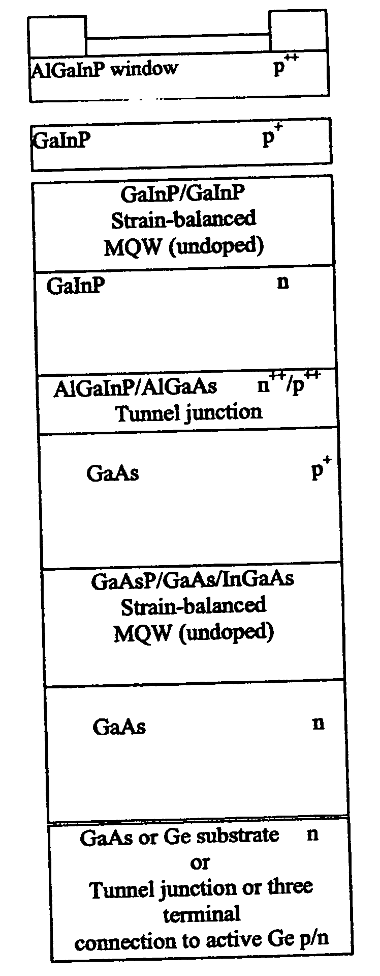
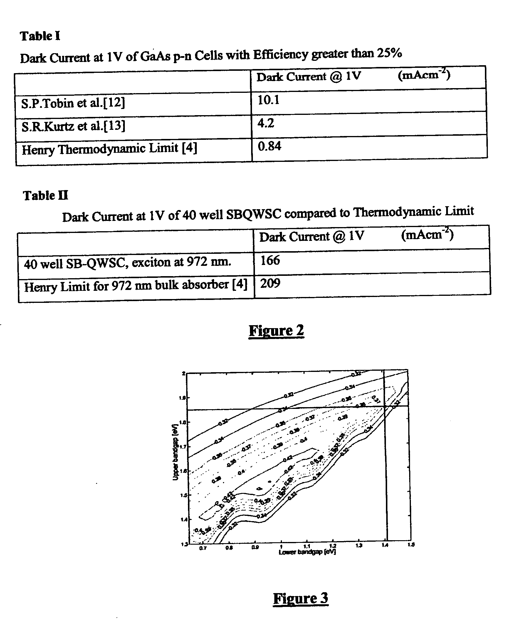
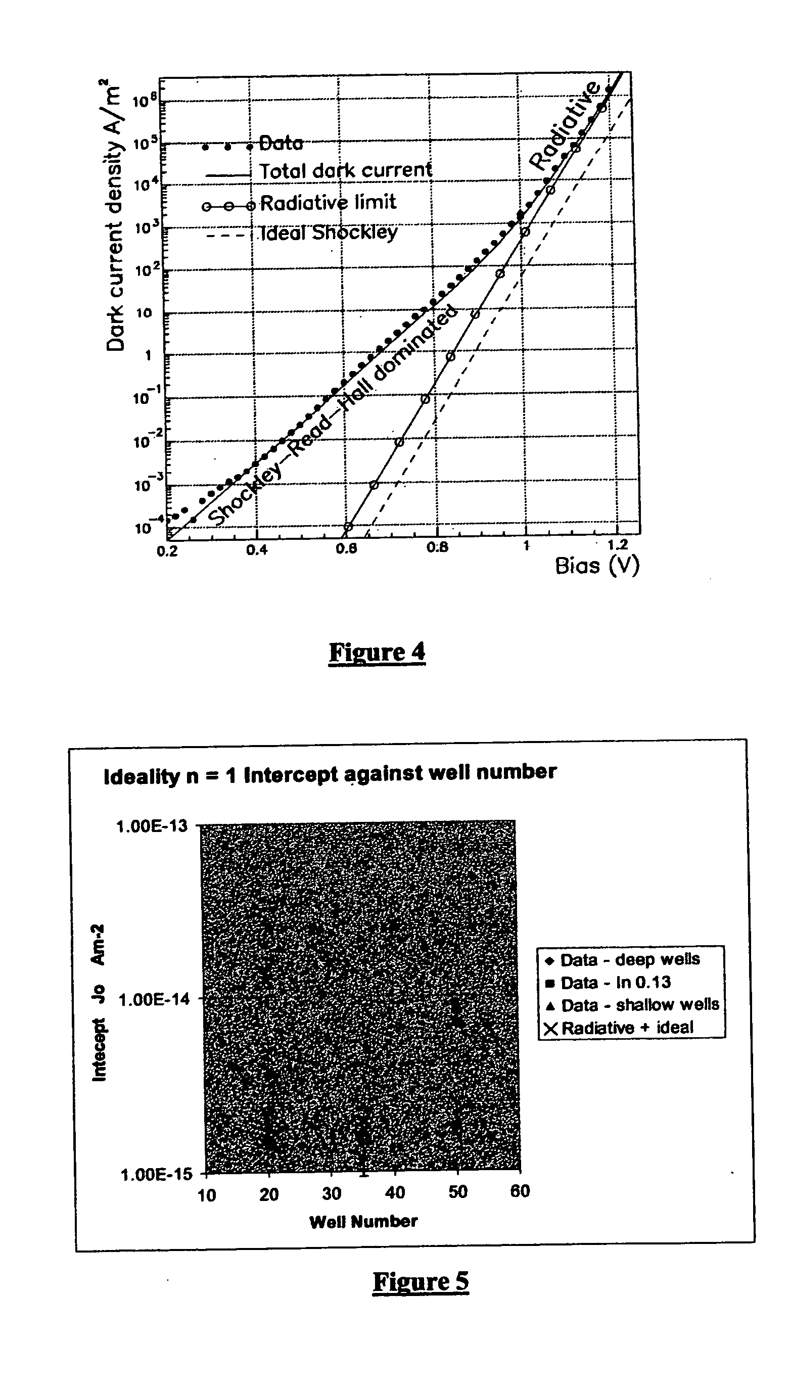
[0035] Here we describe a photovoltaic cell, strain-balanced quantum well solar cell (SB-QWSC) that can substantially simultaneously fulfil the absorption edge and recombination conditions previously discussed. This cell can achieve both conditions with current III-V or II-VI materials. One embodiment of the SB-QWSC is that it has a p and n doped region formed from GaAs and an undoped i-region formed from a GaAs1-xPx / InyGa1-yAs strain-balanced quantum well system where the P composition (x) and the In composition (y) are chosen to ensure that the GaAsP barrier has higher band-gap than the bulk region of the cell and that there is minimum shear force between adjacent layers [6]. The difference in the band gap of the deepest well in the quantum well structure and the band gap of the surrounding bulk semiconductor regions is greater than 60 meV, the bandgap of the bulk semiconductor being greater. The typical number of wells in such a system is around 50. As a result of strain-balancin...


PUM


Abstract

A method of operating a solar cell is provided in which strain balanced multiple quantum well stacks containing greater than 30 quantum wells disposed between bulk semi-conductor regions having a band gap differences between the deepest well of the stack and the bulk semi-conducting region of greater than 60 mev is irradiated with radiation having an intensity of greater than 100 suns. Photons are absorbed with and outside of the quantum well stack to generate electron hole pairs recombination of electrons and holes is substantially only via a radiative recombination mechanism.

Description

BACKGROUND OF THE INVENTION [0001] 1. Field of the Invention [0002] This invention relates to the field of solar cells for generating electrical energy. More particularly, this invention relates to a method of operating a solar cell containing a strain balanced multiple quantum well stack. [0003] Description of the Prior Art [0004] It is known that the optimum band-gap for a single-junction solar cell in typical terrestrial illumination at light concentrations between 30 and 1000× is equivalent to an absorption edge of around 1.1 μm as is shown in FIG. 1 of the accompanying drawings [1]. In order to achieve improved efficiencies within solar cells, which are significantly higher than the current record for a single junction cell of 27.6% at 255× GaAs cell [2], requires that the absorption edge should be moved close to 1.1 μm together with a reduction in recombination losses. [0005] There are no binary or ternary III-V compounds that can reach the band-gap required for such an absorp...

Claims


Application Information

Patent Timeline
Patent Type & Authority Applications(United States)
IPC IPC(8): H01L31/00H01L31/0216H01L31/0352H01L31/072
CPCB82Y20/00H01L31/02168Y02E10/544H01L31/0725H01L31/0735H01L31/035236
Inventor BARNHAM, KEITH WILLIAM JOHNMAZZER, MASSIMOCONNOLLY, JAMES PATRICK
Owner IMPERIAL INNOVATIONS LTD
Learn More