
Systems and methods for detection of combustor stability margin

Active Publication Date: 2005-11-10
GEORGIA TECH RES CORP
View PDF6 Cites 37 Cited by
  • Summary
  • Abstract
  • Description
  • Claims
  • Application Information

AI Technical Summary

Benefits of technology

[0010] The stability margin may be estimated from the time rate of change of the estimated damping coefficient. An increase of the damping coefficient over time may signify the combustor's approach to stable conditions and a decrease of the damping coefficient over time may signify the combustor's approach to unstable conditions.
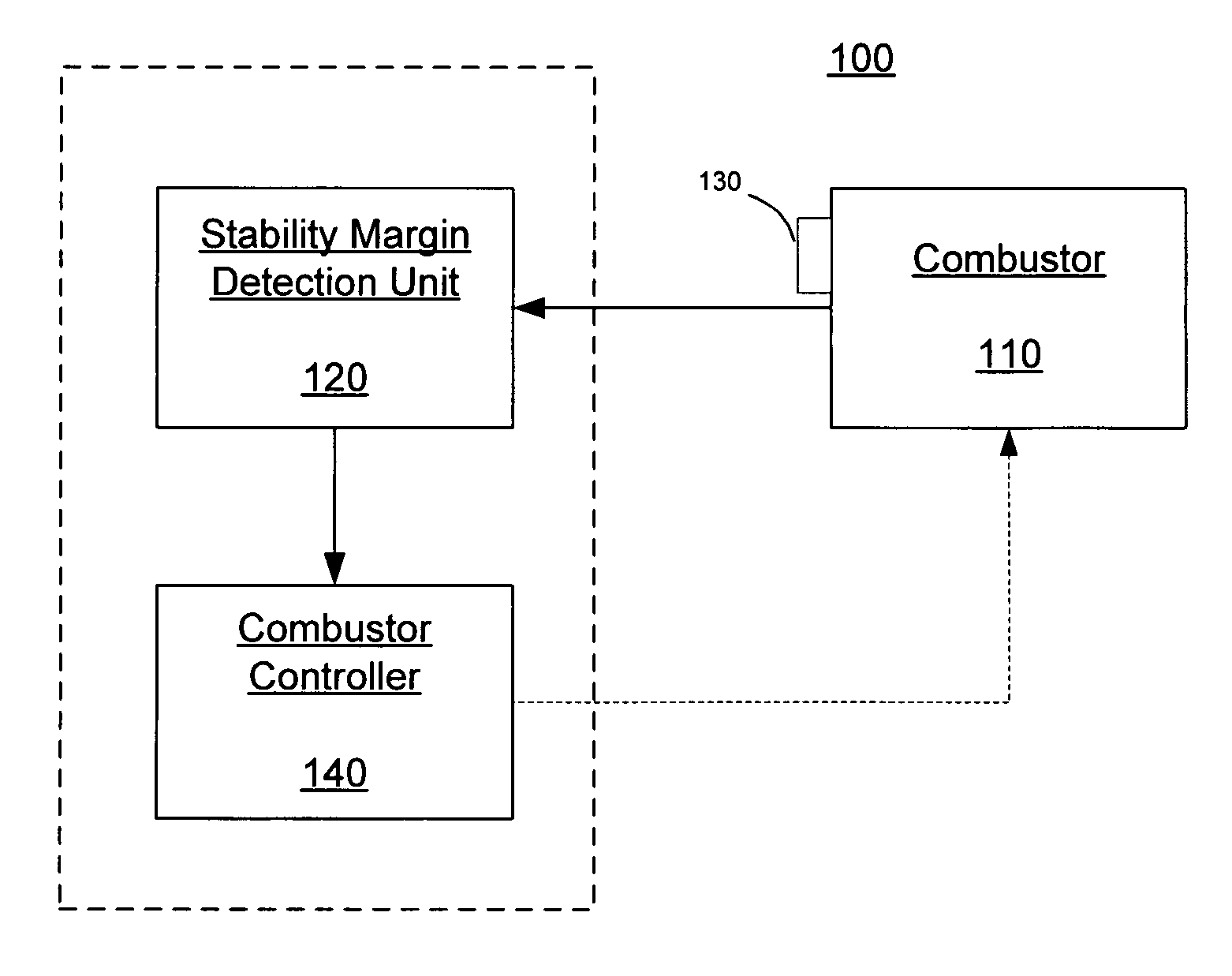
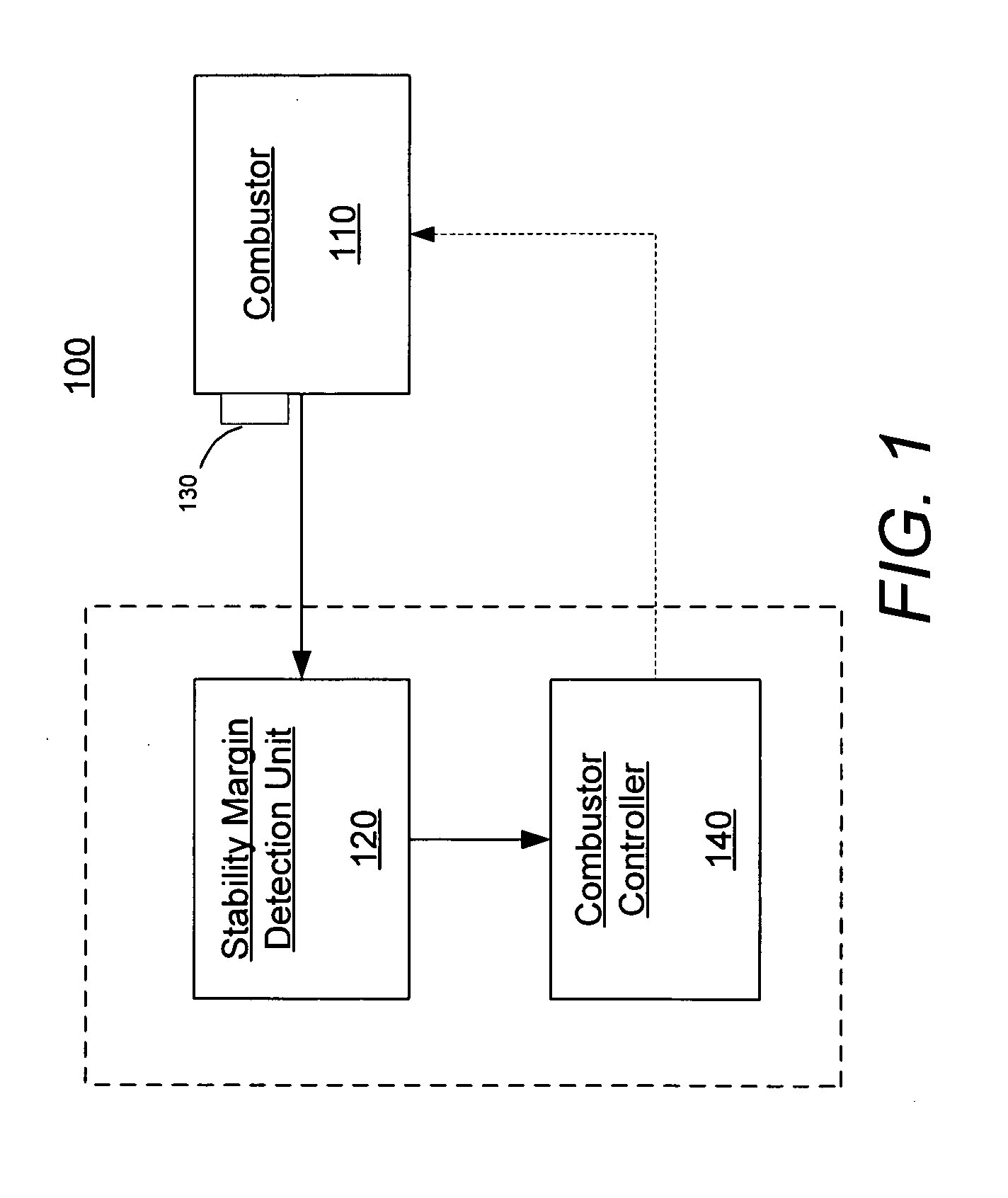
[0011] In yet another aspect of the invention, the measuring device may measure a combustor quantity such as pressure, chemiluminescence, species concentration, temperature, ion current, rotor vibration, combustor can vibration, and casing vibration. In another aspect of the invention, a combustor controller may control combustor parameters to prevent instability in response to the increase of the damping coefficient over time. The combustion parameters may include engine fuel splits, power output, or other parameters that influence combustor stability. Another embodiment of the present invention includes a system for detecting stability margin in a combustor. The system includes a measuring device in communication with the combustor, wherein the measuring device generates signals indicative of a combustor

Problems solved by technology

One key issue that has emerged in combustion systems is that of combustion instabilities—that is, self-excited, combustion driven oscillations that generally occur at discrete frequencies associated with the combustor's natural acoustic modes.
Minimizing the amplitude of these oscillations is essential for maximizing hot section part life—however, tradeoffs between dynamics amplitude, emissions, and power output are routinely encountered.
Currently, when turbines are being commissioned or simply going through day to day operation, the operator has no idea how the stability of the system is affected by changes to fuel splits / operating conditions unless, of course, the system actually becomes unstable.
Such external actuation is not a practical practice for operating combustors in day to day operations.
As such, this technique may be useful in a lab setting but is not practical for a fielded system.
However, the use of frequency domain techniques to determine damping are much more susceptible to noise and less robust than those described here.

Method used


Image

  • Systems and methods for detection of combustor stability margin
  • Systems and methods for detection of combustor stability margin
  • Systems and methods for detection of combustor stability margin

Examples


Embodiment Construction

[0027] The present invention now will be described more fully hereinafter with reference to the accompanying drawings, in which preferred embodiments of the invention are shown. This invention may, however, be embodied in many different forms and should not be construed as limited to the embodiments set forth herein; rather, these embodiments are provided so that this disclosure will be thorough and complete, and will fully convey the scope of the invention to those skilled in the art.

[0028] The present invention is described below with reference to block diagrams and flowchart illustrations of systems, methods, apparatuses and computer program products according to an embodiment of the invention. It will be understood that each block of the block diagrams and flowchart illustrations, and combinations of blocks in the block diagrams and flowchart illustrations, respectively, can be implemented by computer program instructions. These computer program instructions may be loaded onto ...


PUM


Abstract

The present invention comprises systems and methods for determining stability margin of a combustor. One embodiment of the present invention includes the steps of providing a measuring device in communication with the combustor, wherein the measuring device generates signals indicative of combustor quantities; performing an autocorrelation calculation on the signals to determine the correlation time of the signals in the combustor; and determining the damping coefficient from the autocorrelation calculation, wherein the damping coefficient signifies a proximity of the combustor to instability. The damping coefficient may be estimated from the oscillatory envelope of the autocorrelation calculation data.

Description

RELATED APPLICATION DATA [0001] The present application claims benefit of U.S. Provisional Application No. 60 / 542,393, entitled “Method for Monitoring Combustion Dynamics Stability Margin,” filed on Feb. 6, 2004, and incorporated herein by reference as if set forth in full.TECHNICAL FIELD [0002] This invention relates to combustors in gas turbine engines, afterburners, industrial processing devices, and other combustor devices, and more particularly, to systems and methods of monitoring the dynamic stability margin in such combustors. BACKGROUND OF THE INVENTION [0003] In order for turbine operators and / or control systems to optimize overall system performance across competing demands of emissions levels, power output, and engine life, maximum information about each component's health and performance is needed. One key issue that has emerged in combustion systems is that of combustion instabilities—that is, self-excited, combustion driven oscillations that generally occur at discret...

Claims


Application Information

Patent Timeline
IPC IPC(8): F02C9/00F23N5/00
CPCF23N2041/20F23N5/00F23N2241/20
Inventor LIEUWEN, TIM C.
Owner GEORGIA TECH RES CORP
Learn More