Coaxial connector
a technology of coaxial connectors and connectors, which is applied in the direction of coupling device connections, scaffold accessories, building scaffolds, etc., can solve the problems of plugs falling off, troublesome assembly of receptacles, and unsatisfactory high-frequency performance, and achieve satisfactory high-frequency performance, satisfactory high-frequency performance, and satisfactory high-frequency performan
- Summary
- Abstract
- Description
- Claims
- Application Information
AI Technical Summary
Benefits of technology
Problems solved by technology
Method used
Image
Examples
first embodiment
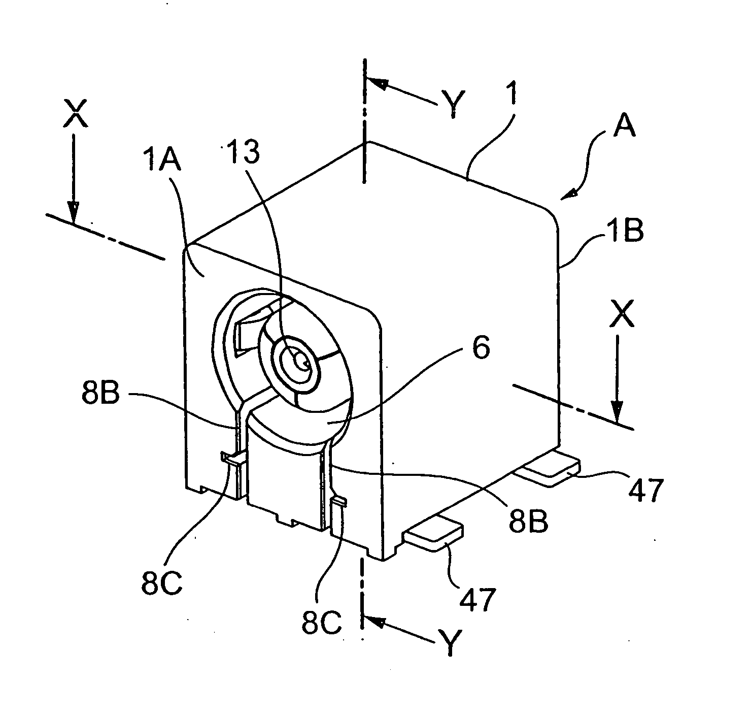
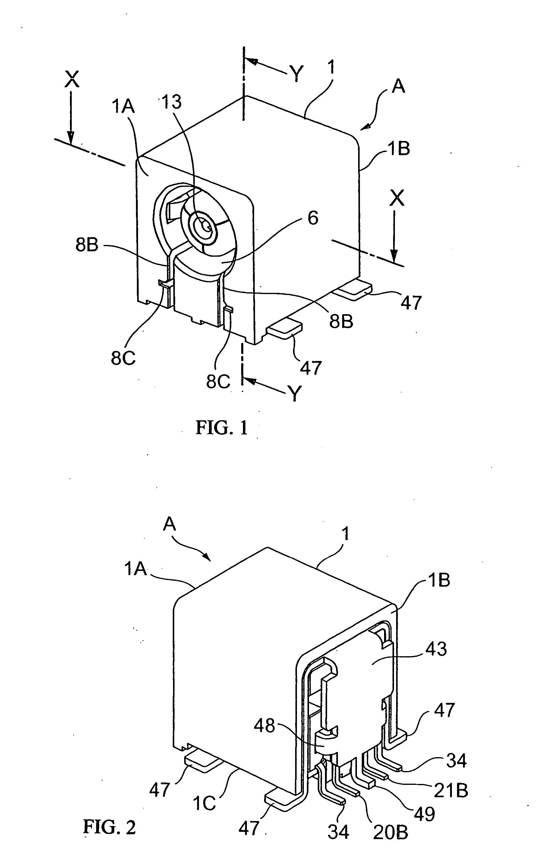
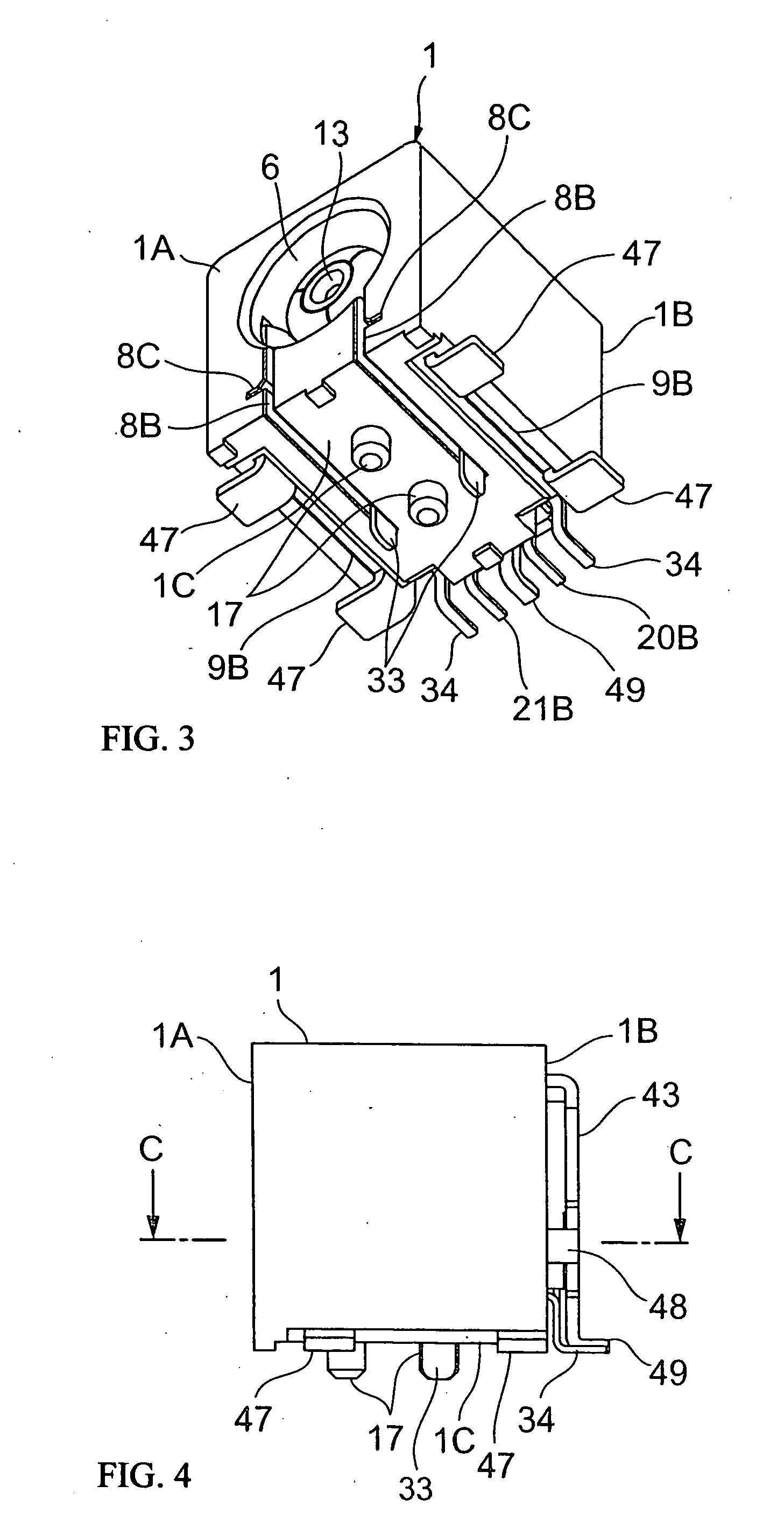
[0080] The first embodiment of the coaxial connector of the invention is shown in FIGS. 1-15.
[0081] The receptacle A, which is the coaxial connector of the invention, is to join to a plug B, which is the counter connector. As shown in FIG. 5, the receptacle A is comprised of an insulating housing 1, an inner conductor 2, and a first and a second outer conductors, which constitutes an outer conductor.
[0082] As shown in FIGS. 7 and 8, the insulating housing 1 has an inner housing section 5, and a counter connector fitting concave section 6 provided to surround the inner housing 5. An inner conductor attaching section 7 is formed at the center portion of the inner housing section 5. In addition, a first and a second outer conductor attaching sections 8 and 9 are formed so as to surround the inner conductor attaching section 7.
[0083] As shown in FIGS. 3, 5, and 7-9, the first outer conductor attaching section 8 is formed from the front section 1A toward the backside section 1B of the...
second embodiment
[0113] The second embodiment of the coaxial connector of the invention is shown in FIGS. 16-24. Here, similar elements to those in the first embodiment are denoted by the same referential numerals, and the explanation is omitted.
[0114] In the second embodiment of the invention, the contact means to contact the first outer conductor 3 with the second outer conductor 4 is formed by contacting the pair of contact sections 48 of the backside shielding section 43 of the second outer conductor 4 with the side shielding section 31B (side portion of the first outer conductor 3); and contacting the edge shielding section 31A of the first outer conductor 3 with the backside shielding section 43 via a conductive contact means F.
[0115] More specifically, as shown in FIGS. 16-17, the conductive contact section F has a contact shoe 70, which is provided at the center of the edge 31e of the edge shielding section 31A of the first outer conductor 3, which faces the second outer conductor 4, so as...
third embodiment
[0134] The third embodiment of the coaxial connector of the invention is shown in FIGS. 30-32.
[0135] The difference of the third embodiment from the above-described first embodiment is that the second outer conductor 4-1 of the third embodiment does not have the backside shielding section 43, and the contact section 48 and the lead section 49 provided on the backside shielding section 43.
[0136] Accordingly, the contact between the pair of contact sections 48 of the backside shielding section 43 and the side shielding section 31B of the first outer conductor 3 is not made. In addition, the contact of edges of the edge shielding section 31A of the first outer conductor 3 and the side shielding section 31B with the inner surface of the backside shielding section is not made. Also, the contact between the first outer conductor 3 and the second outer conductor 4 is not made.
[0137] The constitution and operation of the third embodiment are same as those of the first embodiment except t...
PUM
 Abstract
Description
Claims
Application Information
 - R&D
- Intellectual Property
- Life Sciences
- Materials
- Tech Scout
- Unparalleled Data Quality
- Higher Quality Content
- 60% Fewer Hallucinations
Browse by: Latest US Patents, China's latest patents, Technical Efficacy Thesaurus, Application Domain, Technology Topic, Popular Technical Reports.
© 2025 PatSnap. All rights reserved.Legal|Privacy policy|Modern Slavery Act Transparency Statement|Sitemap|About US| Contact US: help@patsnap.com


