
Image processing method, apparatus, and program

a processing method and image technology, applied in the field of image processing, can solve the problems of not being able to hold the cellular phone during photography, the shutter speed of the cellular camera is slower than that of the ordinary digital camera, and the image may become fuzzy, etc., to achieve the effect of efficient checking the effect of blur correction processing

Active Publication Date: 2005-11-03
FUJIFILM CORP
View PDF9 Cites 26 Cited by
  • Summary
  • Abstract
  • Description
  • Claims
  • Application Information

AI Technical Summary

Benefits of technology

[0016] In view of the foregoing circumstances, it is an object of the present invention to provide an image processing method, apparatus, and program for efficiently check the effects of blur correction processing performed on digital photograph images.
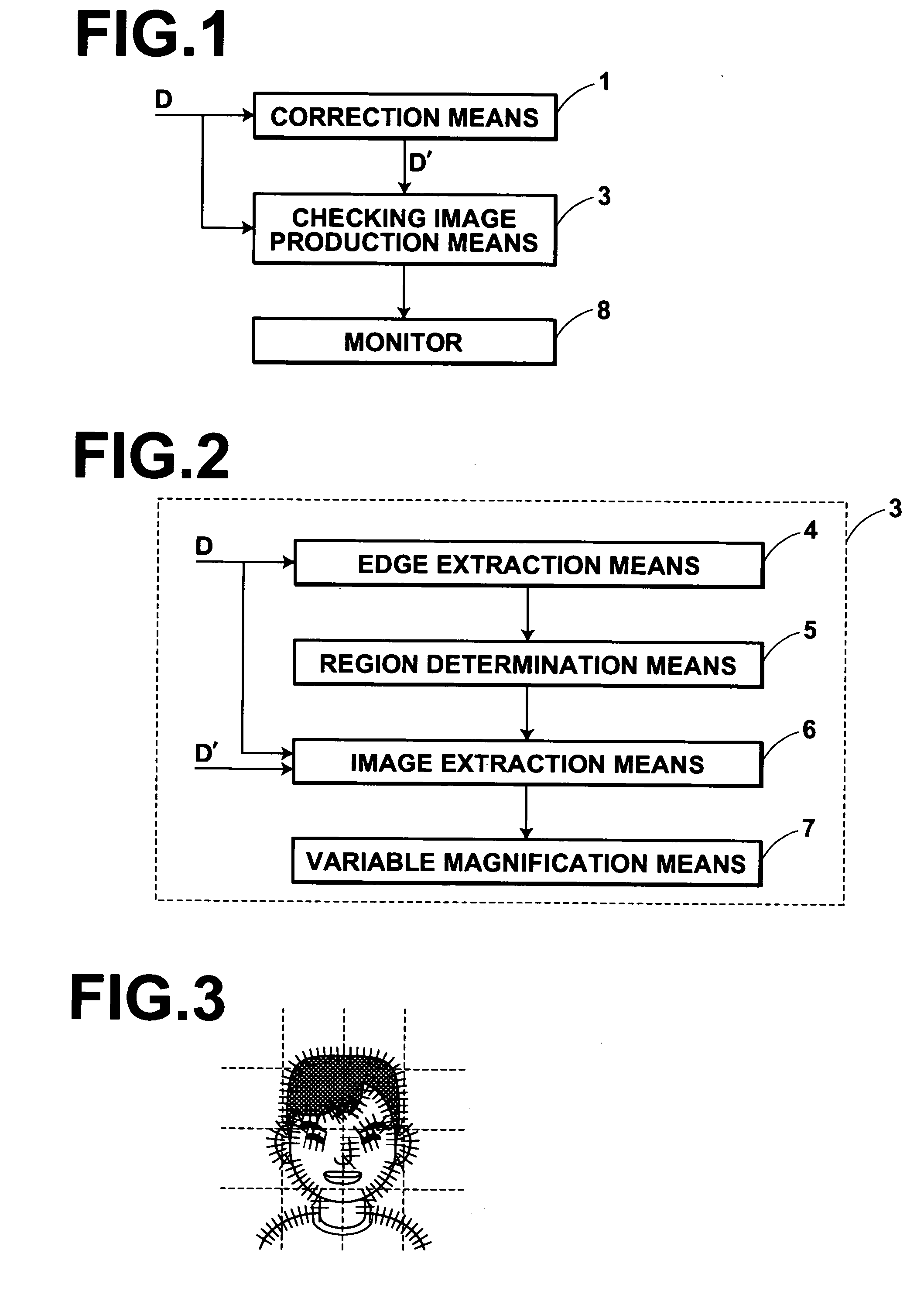
[0048] According to the image processing method and apparatus of the present invention, a region for checking blurs is determined by selecting a region of a digital photograph image before correction processing as a blur checking region for checking the effects of correction processing performed on the digital photograph image. The region selected as the blur checking region is a region in which a blur tends to clearly appear. Then, an image in a region corresponding to the determined blur checking region is extracted from the corrected image as a blur checking image. The extracted image is displayed on a display device in a size appropriate for the size of the display device. If the effect of correction processing is sufficient, blurs in the whole digital photograph image are eliminated or reduced. However, the effects of correction processing are reflected more in an image of a region in the corrected image, which corresponds to the region of the image before correction processing, in which the blur tends to clearly appear. The region in which the blur tends to clearly appear is a region such as a hair region and the region of facial contours. The effects of correction processing are reflected less in a region of the corrected image, which corresponds to the region of the image before correction processing, in which the blur does not tend to appear or does not tend to clearly appear. The region in which the blur does not tend to appear or does not tend to clearly appear is a region such as the upper left corner in the image illustrated in FIG. 3 and blocks at the ends of the image. Therefore, if the effects of correction processing are checked by extracting an image of a region corresponding to a region of the image before correction processing, in which the blur tends to clearly appear, from the corrected image, the effects of correction processing can be accurately judged. Further, since a part (checking image) of the corrected image can be displayed on the display device in a size appropriate for the size of the display device, even if the display device is a device such as the monitor of a cellular camera, of which the resolution is low, the effects of correction processing can be correctly checked.
[0049] Further, in the image processing method and apparatus according to the present invention, the blur checking image is automatically extracted from the corrected image, and displayed. Therefore, the users are not required to specify the regions. Further, it is not required to sequentially display the regions of the image. Therefore, image processing can be performed efficiently.
[0050] Further, if an image of the blur checking region is extracted from the digital photograph image before correction processing, and the extracted image is displayed together with the checking image extracted from the corrected image, the users can compare the condition of the blurs between the image before correction processing and the corrected image. Therefore, the users can more accurately check the effects of blur correction processing.

Problems solved by technology

When photograph images are obtained by photographing a subject, the images may become fuzzy because of an out-of-focus blur or a blur due to hand motion.
However, since the main bodies (cellular phones) of the cellular cameras are not ergonomically designed as specialized photography devices, there is a problem that it is not easy to hold the cellular phones during photography.
Further, since no strobes are provided in the cellular cameras, the shutter speeds of the cellular cameras are slower than those of the ordinary digital cameras.
However, if the motion blur is small, he / she often does not notice the blur in the image displayed on the monitor, and he / she notices the blur only when the image is printed.
Therefore, it is not practical to install a device for obtaining the direction and width of a motion blur in the camera attached to the cellular phones.
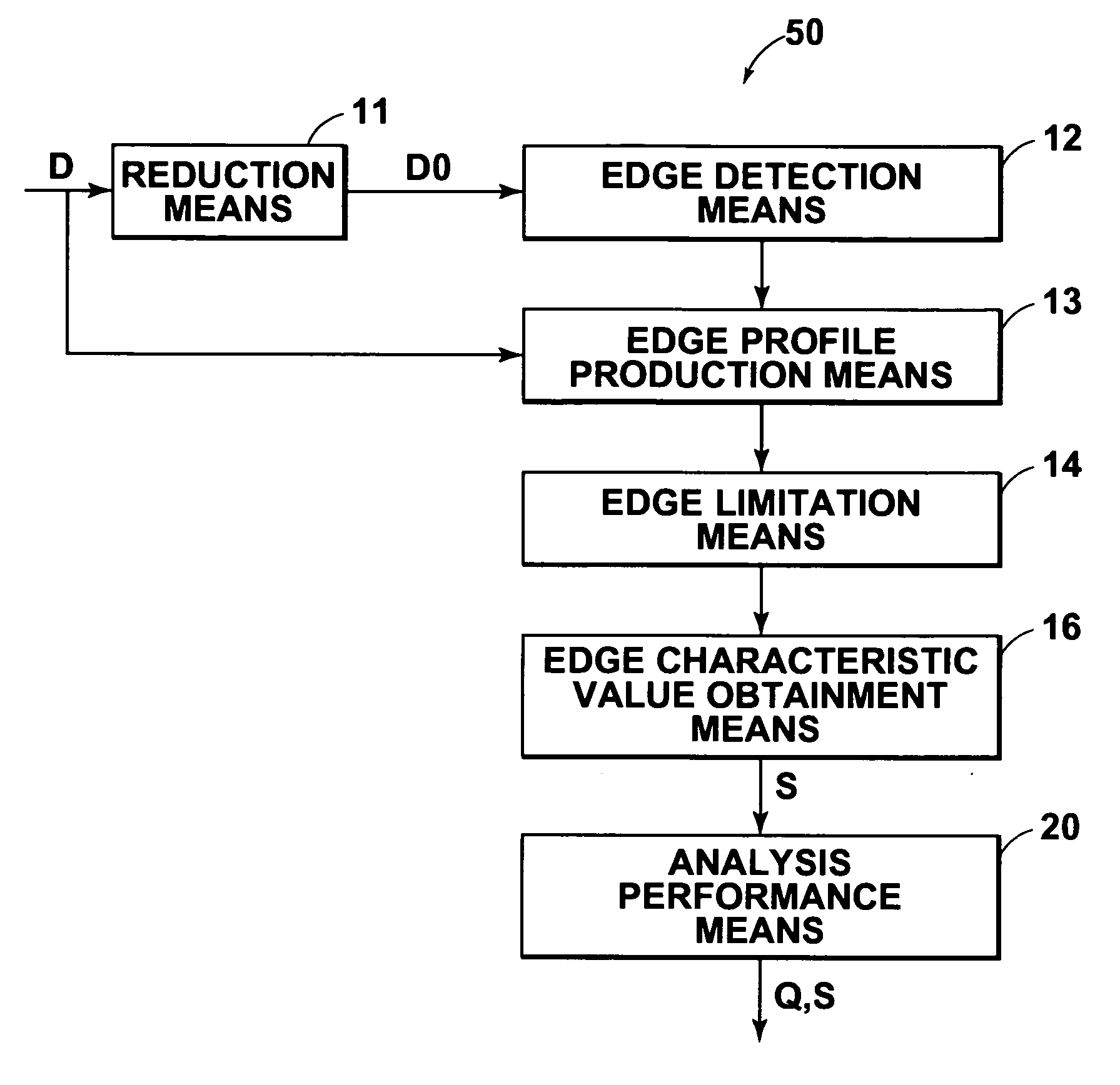
Therefore, there is a problem that processing time becomes long, and the efficiency of processing drops.
Since the reduced image is displayed on the monitor of the cellular camera, it is impossible to check the effects of blur correction processing.
However, in the method of making users specify display regions, the users are required to specify the regions which will be checked, and that is troublesome for the users.
Further, although blurs are evenly distributed in the whole regions of the images, there are regions in which the blurs can be easily detected, and there are also regions in which the blurs cannot be easily detected, or cannot be detected at all.
When the users check the effects of blur correction processing performed on the image as illustrated in FIG. 3, if they check a region such as the block in the upper left corner, in which the blur does not tend to clearly appear, it is impossible to know whether the blur is corrected.
It is also impossible to know the magnitude of correction.
Further, in the method of making the users specify display regions, the users cannot always accurately specify the regions which are appropriate for checking the effects of blur correction processing.
Therefore, the users may erroneously specify the regions by making wrong judgments.
Further, in a method of displaying a region at a predetermined position of an image by extracting it from the image, as disclosed in U.S. patent application Publication No. 20030184667, there is a problem that if the region at the predetermined position of the image is not appropriate for checking the effects of blur correction processing, the users cannot accurately judge the effects of correction processing.
Further, in the method of dividing an image into a plurality of regions and sequentially displaying the divided regions, there is a problem that a long time is required for processing.
Further, the load of processing on the apparatus is heavy, and the operation is troublesome for the users.

Method used


Image

  • Image processing method, apparatus, and program
  • Image processing method, apparatus, and program
  • Image processing method, apparatus, and program

Examples


first embodiment

[0069]FIG. 1 is a block diagram illustrating the configuration of an image processing apparatus in the present invention. The image processing apparatus according to the present embodiment performs blur correction processing on digital photograph images (hereinafter referred to as images, for short). The image processing apparatus also makes users check the effects of blur correction processing. As illustrated in FIG. 1, the image processing apparatus includes a correction means 1 for obtaining a corrected image D′ by performing blur correction processing on an image D which has been input. The image processing apparatus also includes a checking image production means 3 for producing a checking image using the corrected image D′ and the image D. The checking image is an image for checking the effects of blur correction processing performed by the correction means 1. The image processing apparatus also includes a monitor 8 for displaying the checking image produced by the checking im...

second embodiment

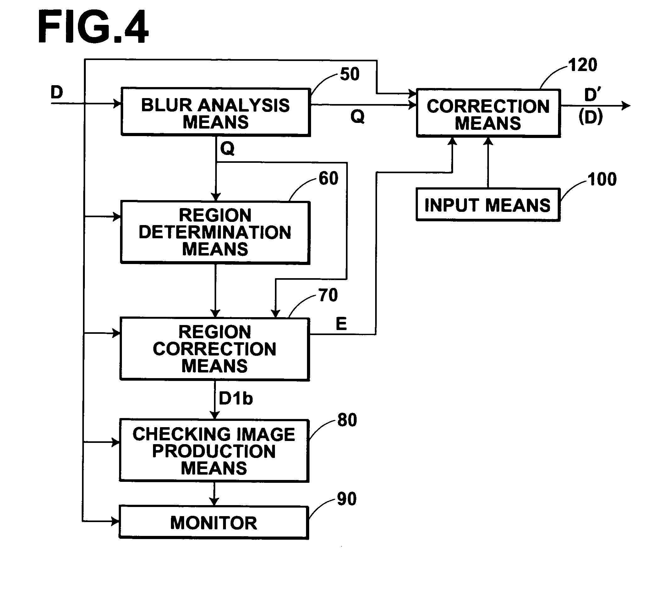
[0075]FIG. 4 is a block diagram illustrating the configuration of an image processing apparatus in the present invention. As illustrated in FIG. 4, the image processing apparatus according to the present embodiment includes a blur analysis means 50 for analyzing the condition of blurs in the input image D. The image processing apparatus also includes a region determination means 60. The region determination means 60 determines a region (hereinafter referred to as an object region) which is an object of correction processing which will be performed by a region correction means 70, which will be described later. The image processing apparatus also includes the region correction means 70 for obtaining a corrected image D1b by performing blur correction processing on an image of the object region in the image D, determined by the region determination means 60. The image processing apparatus also includes a checking image production means 80. The checking image production means 80 extrac...


PUM


Abstract

A blur checking region is determined by selecting a region in which a blur tends to clearly appear in a digital photograph image as the blur checking region. Then, an image of a region corresponding to the blur checking region is obtained as a checking image in a corrected image obtained by performing blur correction processing on the digital photograph image. Then, the obtained checking image is displayed in a size appropriate for the resolution of a display device.

Description

BACKGROUND OF THE INVENTION [0001] 1. Field of the Invention [0002] The present invention relates to image processing. Particularly, the present invention relates to an image processing method, apparatus and program for checking the effect of blur correction processing performed on digital photograph images. [0003] 2. Description of the Related Art [0004] Digital photograph images are obtained by photoelectrically reading out photograph images recorded on photograph films such as negative films and color reversible films with a readout device such as a scanner. Digital photograph images are also obtained by photographing subjects with digital still cameras (DSC). When the digital photograph images are obtained, various kinds of image processing are performed on the digital photograph images, and images after image processing are displayed, printed, or the like. One of the examples of the image processing is blurred image restoration processing for removing a blur from a fuzzy image ...

Claims


Application Information

Patent Timeline
Patent Type & Authority Applications(United States)
IPC IPC(8): G06K9/46G06T5/00G06T7/60H04N1/387G06T5/20H04N1/393H04N1/409H04N1/58
CPCH04N1/4092G06T5/003G06T2207/20201G06T2207/20021G06T7/0085G06T7/13G06T5/73
Inventor AOYAMA, TATSUYA
Owner FUJIFILM CORP
Learn More