
Liquid crystal color display system and method

Active Publication Date: 2005-11-03
HONEYWELL INT INC
View PDF16 Cites 38 Cited by
  • Summary
  • Abstract
  • Description
  • Claims
  • Application Information

AI Technical Summary

Benefits of technology

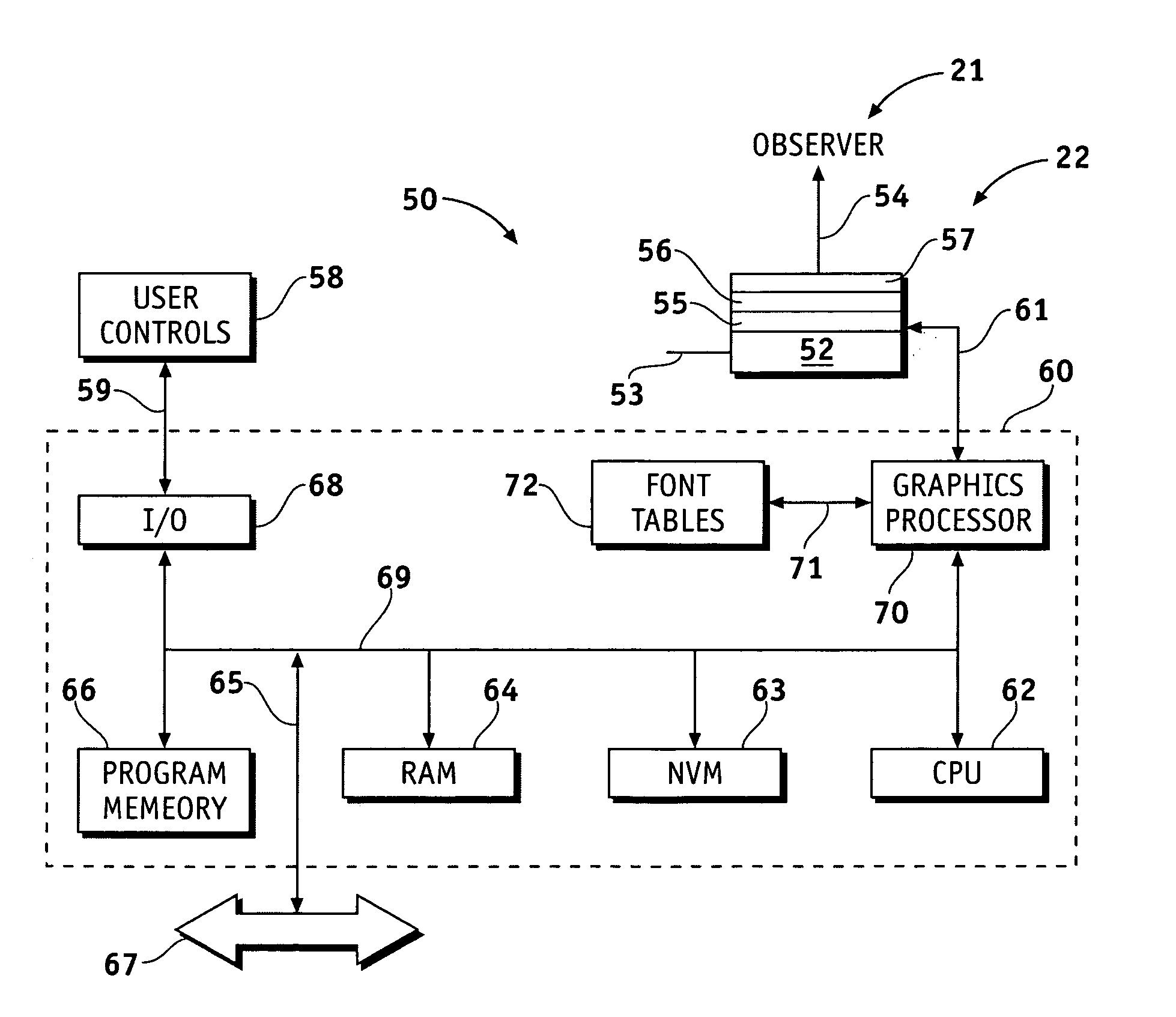
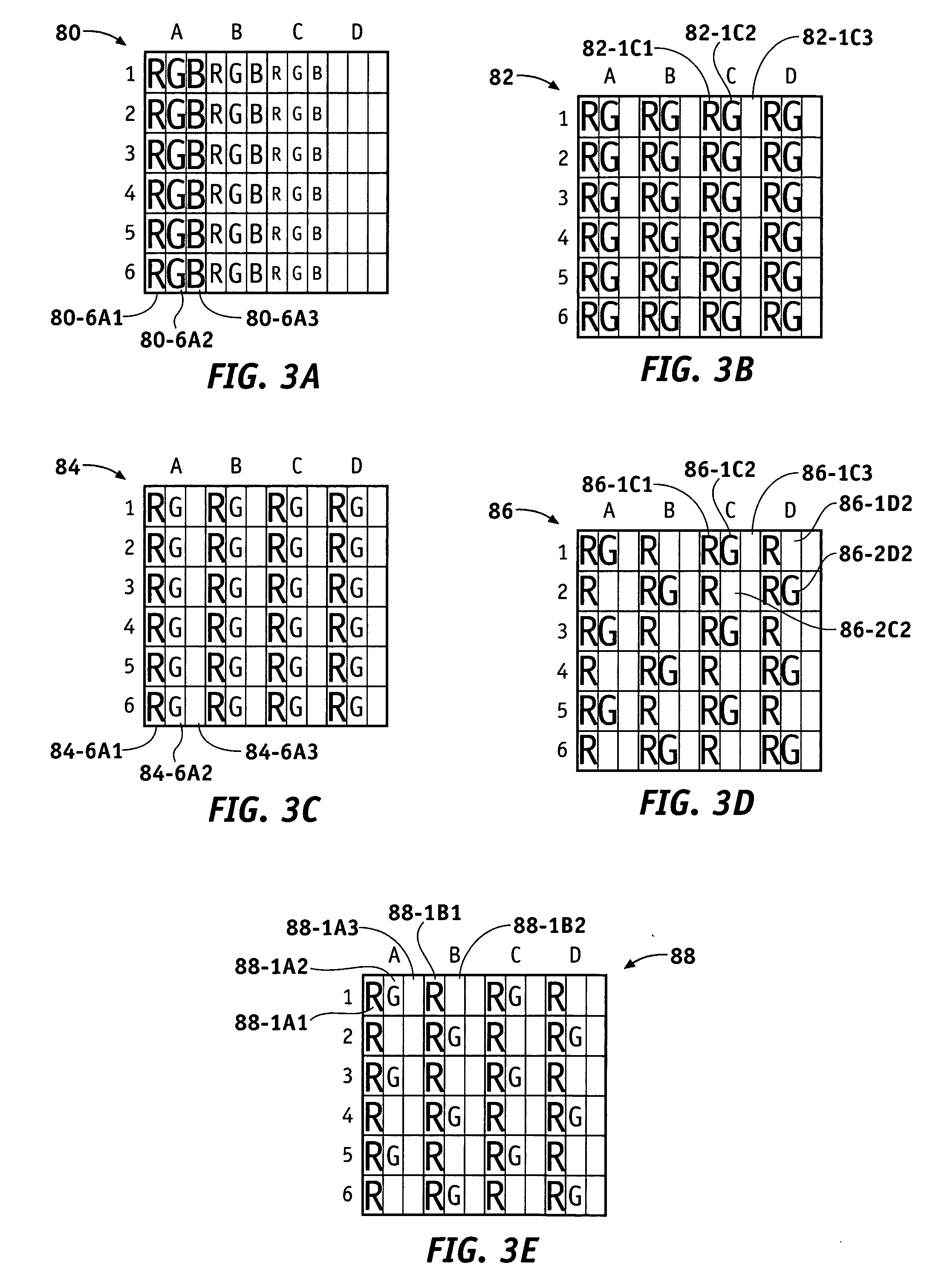
[0005] An apparatus is provided for a color liquid crystal display (CLCD). The apparatus comprises a processor coupled to the CLCD for receiving a character code and a color code and translating them into character and color pixel arrays that are overlaid and summed to produce a composite pixel array corresponding to the CLCD pixel array, where each entry in the composite array is used in conjunction with a color table to establish drive levels for each pixel in the CLCD. The character pixel array includes gray level color mixing as well as defining the character size and shape on the CLCD, and the color pixel array includes spatial shading color mixing, so that the composite array uses both techniques to determine the individual CLCD pixel drive levels, thereby providing a wider range of color choices without significant color dependence on viewing angle.

Problems solved by technology

For example, if the color perceived by the viewer changes depending upon, for example, viewing angle, or the image contrast or luminance, this can potentially lead to mistaken interpretation of the displayed information.
For example, the viewing angle over which color fidelity is reasonably preserved may be undesirably narrow, and / or the absolute color provided by the display can vary depending upon the drive intensity, and / or the number of possible colors that can be displayed may be undesirably limited, and / or the display brightness may be weak and insufficient to permit easy viewing in sunlight or other bright light conditions, and so forth.
Further, color fidelity, color choice, luminance or brightness, viewing angle, and other properties often mutually interact so that prior art approaches for improving one property may cause degradation in another property.

Method used


Image

  • Liquid crystal color display system and method
  • Liquid crystal color display system and method
  • Liquid crystal color display system and method

Examples


Embodiment Construction

[0015] The following detailed description is merely exemplary in nature and is not intended to limit the invention or the application and uses of the invention. Furthermore, there is no intention to be bound by any expressed or implied theory presented in the preceding technical field, background, brief summary or the following detailed description.

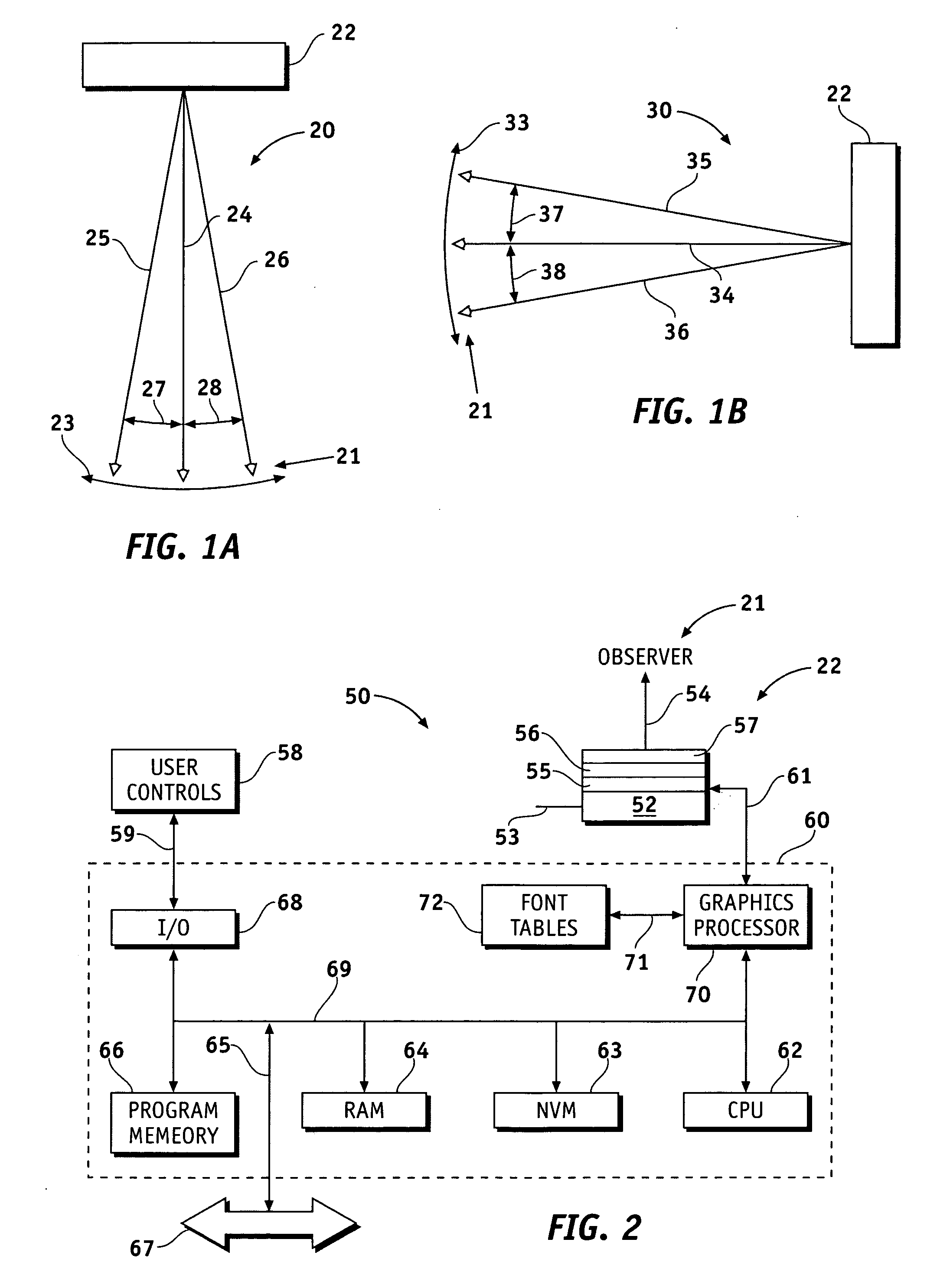
[0016]FIGS. 1A shows simplified plan view 20 and 1B shows simplified side view 30 of observer 21 positioned with respect to liquid crystal display 22. Display 22 emits light at different angles as indicated by rays 24-26 in FIG. 1A and rays 34-36 in FIG. 1B. FIG. 1A shows observer 21 in different azimuthal positions, for example along arc 23, receiving ray 24, or ray 25 or ray 26 depending upon the observer's position. Rays 25, 26 make angles 27, 28 with respect to central ray 24 in FIG. 1A. FIG. 1B shows observer 21 in different vertical positions, for example along arc 33, receiving ray 34, or ray 35 or ray 36 depending upon the observ...


PUM


Abstract

Methods and apparatus are provided for a color liquid crystal display (CLCD). The apparatus comprises a processor coupled to the CLCD for receiving a character code and a color code and translating them into character and color pixel arrays that are overlaid and summed to produce a composite pixel array corresponding to the CLCD pixel array, where each entry in the composite array is used in conjunction with a color table to establish drive levels for each pixel in the CLCD. The character pixel array includes gray level color mixing and the color pixel array includes spatial shading color mixing, so that the composite array uses both techniques to determined the individual CLCD pixel drive levels, thereby providing a wider range of color choices without significant color dependence on viewing angle.

Description

TECHNICAL FIELD [0001] The present invention generally relates to liquid crystal displays, and more particularly to color generation for liquid crystal displays. BACKGROUND [0002] Liquid crystal displays able to show alphanumeric and / or graphical information in various colors are well known in the art. Such liquid crystal color displays are used in avionics, computers, telephones, medical imaging, vehicles, and various other applications. In many cases the displayed colors may convey functional information. For example, and not intended to be limiting, text, numbers, and / or symbols, or a combination thereof may signify a substantially ‘safe’ condition when presented in green, a ‘caution’ condition when presented in yellow or amber, and a potential ‘danger’ condition when presented in red. In such instances, the color of the image is intended to convey information to the user, in addition to or as a supplement to the information provided by the content of the image. Thus, color fidel...

Claims


Application Information

Patent Timeline
IPC IPC(8): G09G3/36G09G5/02G09G5/22G09G5/28
CPCG09G3/3607G09G5/02G09G2320/028G09G5/28G09G5/22
Inventor HAIM, VICTORIA P.TRIPLETT, JAMES L.ZULCH, HAROLD A. III
Owner HONEYWELL INT INC
Learn More