
Directional broadcast feeder for fish and game

a feeder and directional technology, applied in the field of directional broadcast feeders for fish and game, can solve the problems of severe limitations in the conventional scatter feeder and the number of game feeding requirements, and achieve the effect of high efficiency

Active Publication Date: 2005-11-03
TH PROD LLC
View PDF9 Cites 56 Cited by
  • Summary
  • Abstract
  • Description
  • Claims
  • Application Information

AI Technical Summary

Benefits of technology

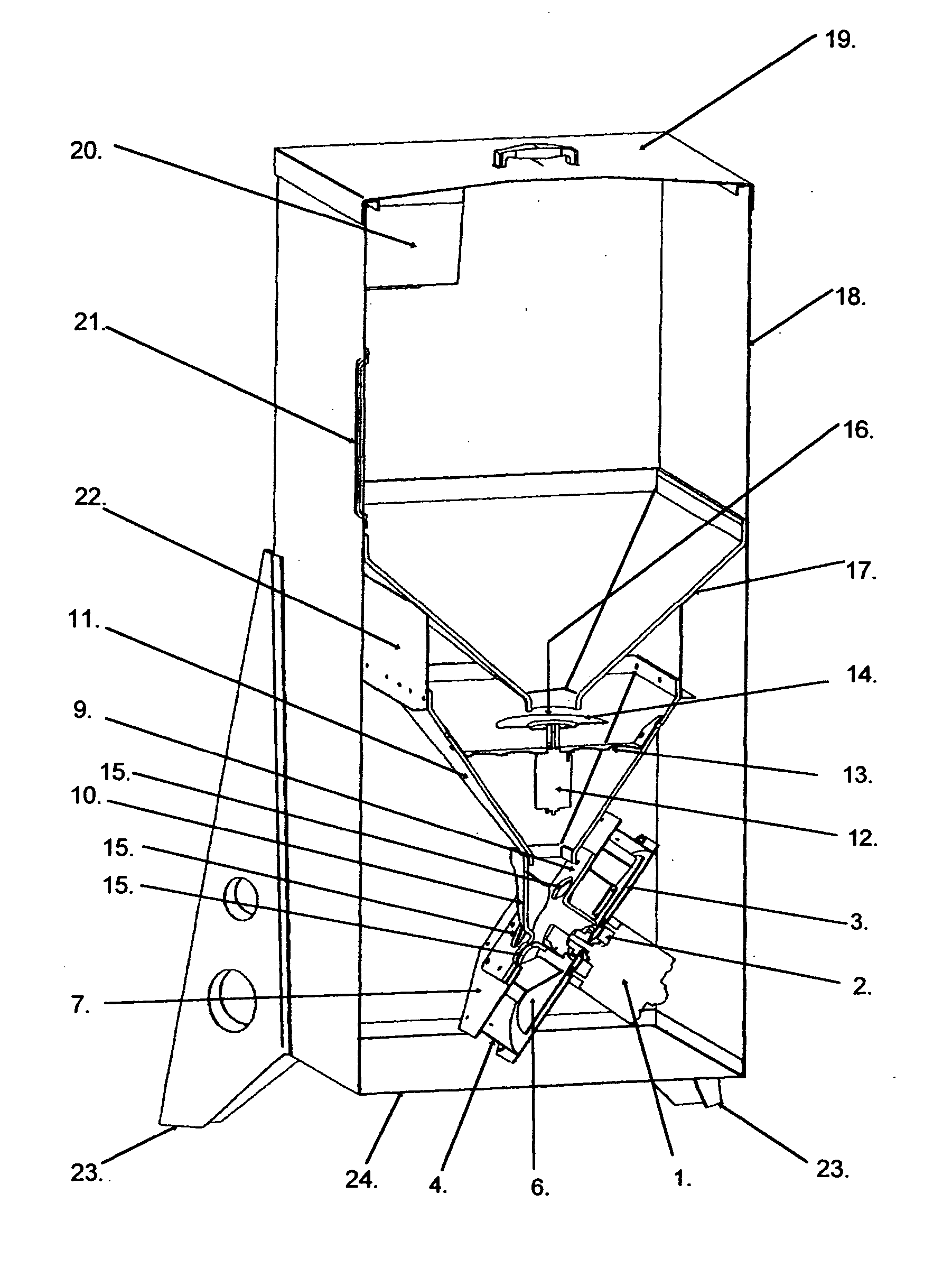
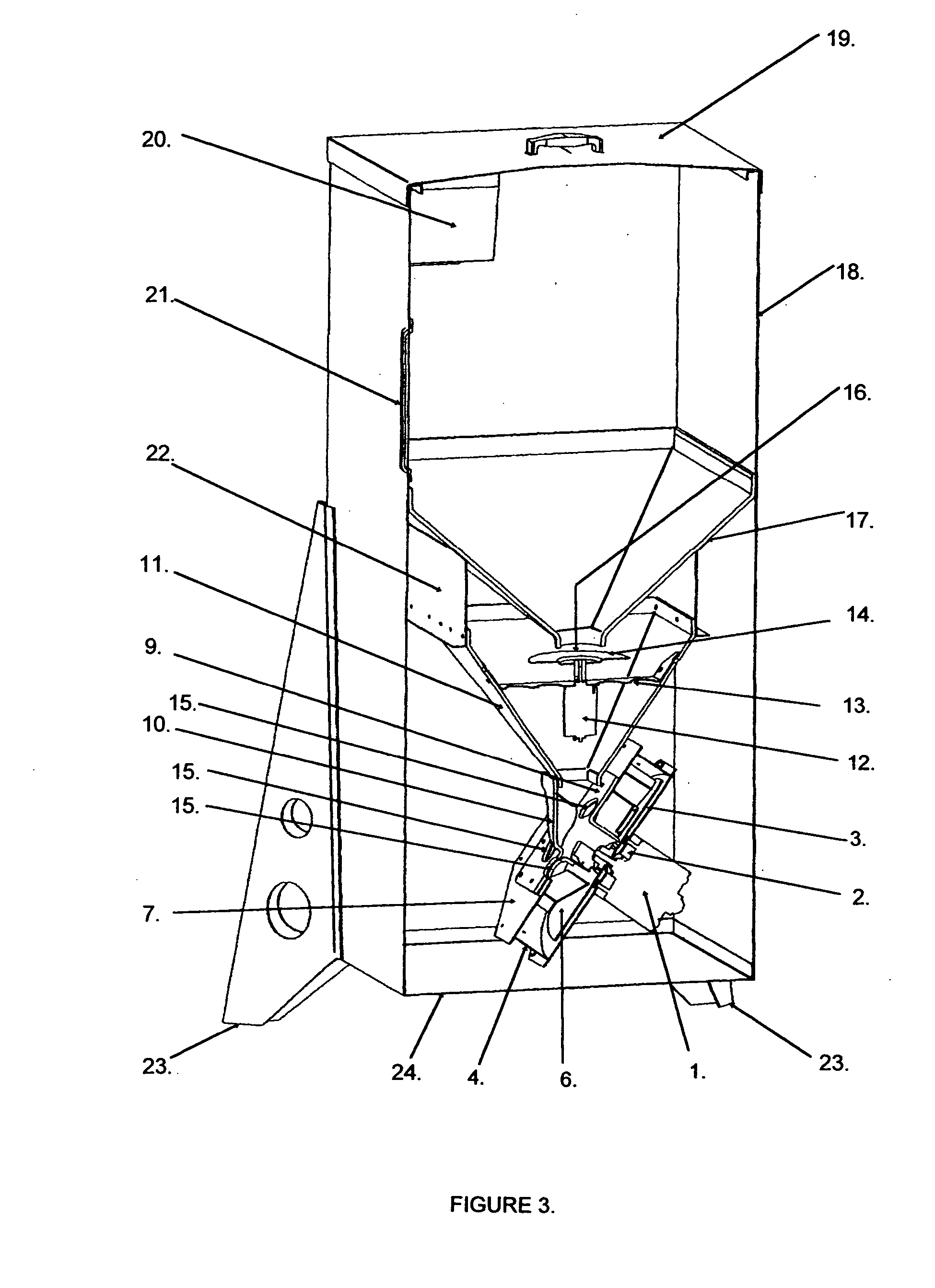
[0005] The application of a center intake centrifugal blower in this invention relies on the introduction of feed particulate or pellets into the low-pressure central intake area. In the air stream, the particulates are accelerated with the airflow along the impeller blades at a high velocity to rapidly exit from the exhaust opening at the front of the feeder. By creating and using a high velocity air stream or air flow to direct and accelerate the feed pellets a high efficiency is achieved with less friction on the impeller and case assembly. To simplify the means of injecting the feed pellets into the center intake opening, the blower assembly is tilted, e.g., thirty degrees, from vertical in reference to the hopper or bulk container. By tilting the blower a direct path is created from the hopper funnel to the blower intake, which eliminates the requirements for complicated chutes and elbows.
[0006] By utilizing a conventional scatter plate at the primary storage hopper funnel as the on / off switch to control the feed flow, the requirement for an actuated gate is eliminated. Further, by eliminating a shut-off gate, the associated baffles, which are often required to lesson the feed weight on the gate, are not required.
[0010] A primary object of the invention is to provide a high efficiency directional feeder module, which does not require the use of special shut off gates, baffles or chutes.
[0011] It is a further object of the invention to provide a means where the projection of the feed particulate is accomplished with a minimum of physical impact, friction or shredding of the feed.
[0012] It is also an object of the invention to provide the means whereby the feed pellets will be smoothly accelerated to a high velocity capable of propelling the feed up to sixty feet from the feeder assembly in a single direction.

Problems solved by technology

There are, however, numerous game feeding requirements where the conventional scatter type game feeders are severely limited.

Method used


Image

  • Directional broadcast feeder for fish and game
  • Directional broadcast feeder for fish and game
  • Directional broadcast feeder for fish and game

Examples


Embodiment Construction

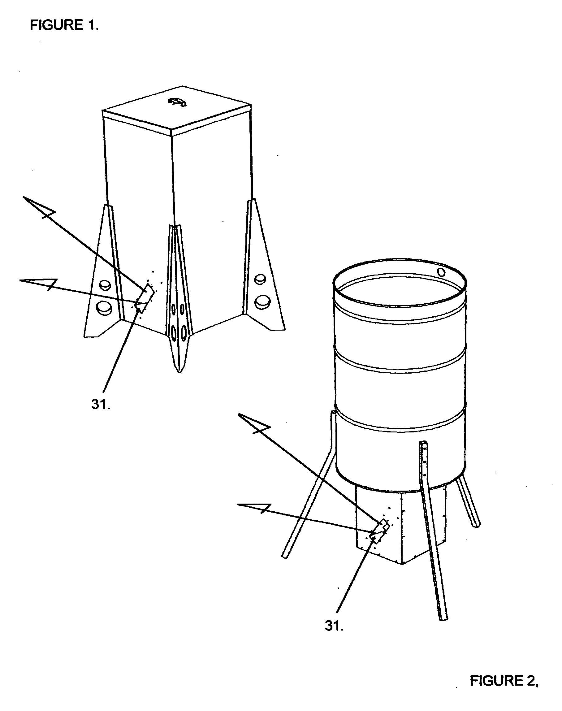
[0021] The directional feeder assemblies shown in FIGS. 1 and 2 show two different embodiments of the present invention. Each embodiment utilizes the same primary centrifugal blower assembly, depicted in the exploded perspective detailed FIG. 5. The output or opening that discharges the feed pellets or aggregate is located at 31.

[0022] Drawing FIG. 3 shows a sectioned view of the embodiment of FIG. 1 which is a self-contained directional feeder of approximately 125 lbs capacity in this case. The feeder consists of an outer case 18 with four attached legs 23 and a removable cover 19. An internal battery and timer 20 power and control the sequence of operation. A transparent sight glass to enable viewing of the hopper feed level is shown at 21.

[0023] Hopper funnel 17 is attached to the outer case 18 at its top rim. Side support is provided by four ribs 22, which are attached to the outer case 18. These ribs 22 are used to attach the secondary collection funnel 11 and blower assembly...


PUM


Abstract

A broadcast feeder for projecting food aggregate or pellets directionally into an area up to, for example, sixty or more feet away from the feed container. The action is controlled to provide a predetermined quantity of aggregate at a predetermined time. The velocity of the feed as it exits the feeder is such that the area directly surrounding the feeder is free of feed particulate. A modular design affords the ability to operate as a self-contained unit with its own storage hopper or as a retrofit module added to existing conventional barrel type scatter type feeders. The projection of the feed is accomplished by propelling the feed pellets with a center intake centrifugal air blower assembly designed such that no special feed gates, baffles or chutes are required.

Description

TECHNICAL FIELD OF THE INVENTION [0001] Various types of active or powered game feeders are available which utilize a battery-powered timer and electric motor to provide energy to scatter or broadcast particulate feed over an area for animal, bird or fish consumption. The simplest of this type of feeder is the scatter plate type feeder, which utilizes a rotating disk of various forms to propel the feed outward in a circular arc around the periphery of the feed station. Directional feeders are also available. Directional feeders use a high speed rotating finned paddle wheel to accelerate and propel the feed unidirectionally from the dispensing apparatus. Functionally the paddles contact the feed and continually impart a force to the food pellets sufficient to ensure they are expelled at a rate that prevents them from accumulating about the food pellet dispensing apparatus. The present invention uses a center feed centrifugal air blower design to create a spiraling high velocity air f...

Claims


Application Information

Patent Timeline
IPC IPC(8): A01K5/00A01K5/02A01K61/02
CPCA01K5/0225A01K61/02A01K5/0291A01K61/80Y02A40/81
Inventor FOSTER, H. DELL
Owner TH PROD LLC
Learn More