
Method of controlling image forming apparatus to determine printing operation depending on residual developer

a technology of image forming apparatus and printing operation, which is applied in the direction of digital output to print units, visual presentations using printers, instruments, etc., can solve the problems of printing data loss, waste of printing papers, etc., and achieve the effect of preventing deterioration of print quality and waste of printing papers

Inactive Publication Date: 2005-10-27
S PRINTING SOLUTION CO LTD
View PDF5 Cites 6 Cited by
  • Summary
  • Abstract
  • Description
  • Claims
  • Application Information

AI Technical Summary

Benefits of technology

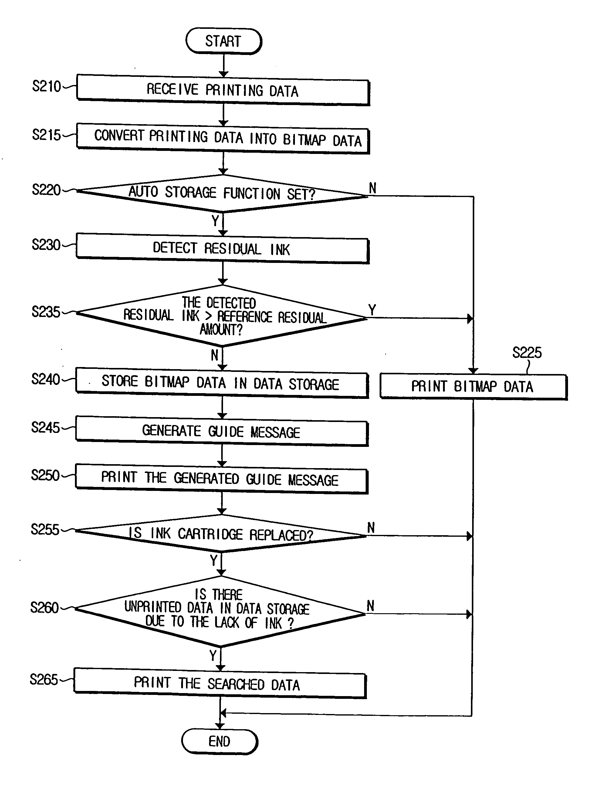
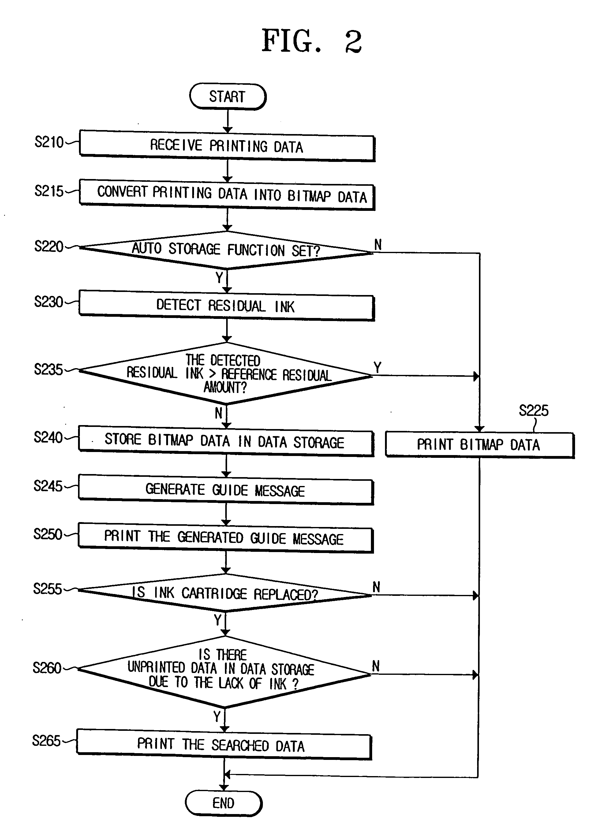
[0008] The present general inventive concept provides a method of controlling an image forming apparatus to determine a printing operation depending on a residual developer so as to prevent deterioration of a print quality due to a lack of the residual developer, and waste of printing papers due to a duplicate printing.
[0018] The storing of the printing data may be prevented the printing data from being printed according to the amount of the detected residual developer.

Problems solved by technology

This is because the printing data can be lost during the printing job when the developer is consumed more than a predetermined amount.
However, the conventional image forming apparatus is implemented to perform the printing jobs unconditionally upon the receipt of the printing data from the external device regardless of the lack of the developer.
If the print quality becomes poor due to the lack of the developer, the printing data has to be retransmitted to the image forming apparatus after replacing a developing device.
Such a situation causes inconvenience since the user has to retransmit the printing data to the image forming apparatus, and also causes waste of printing papers due to the duplicate printing of the same document.

Method used


Image

  • Method of controlling image forming apparatus to determine printing operation depending on residual developer
  • Method of controlling image forming apparatus to determine printing operation depending on residual developer
  • Method of controlling image forming apparatus to determine printing operation depending on residual developer

Examples


Embodiment Construction

[0032] Reference will now be made in detail to the embodiment of the present general inventive concept, examples of which are illustrated in the accompanying drawings, wherein like reference numerals refer to the like elements throughout. The embodiment is described below in order to explain the present general inventive concept by referring to the drawings.

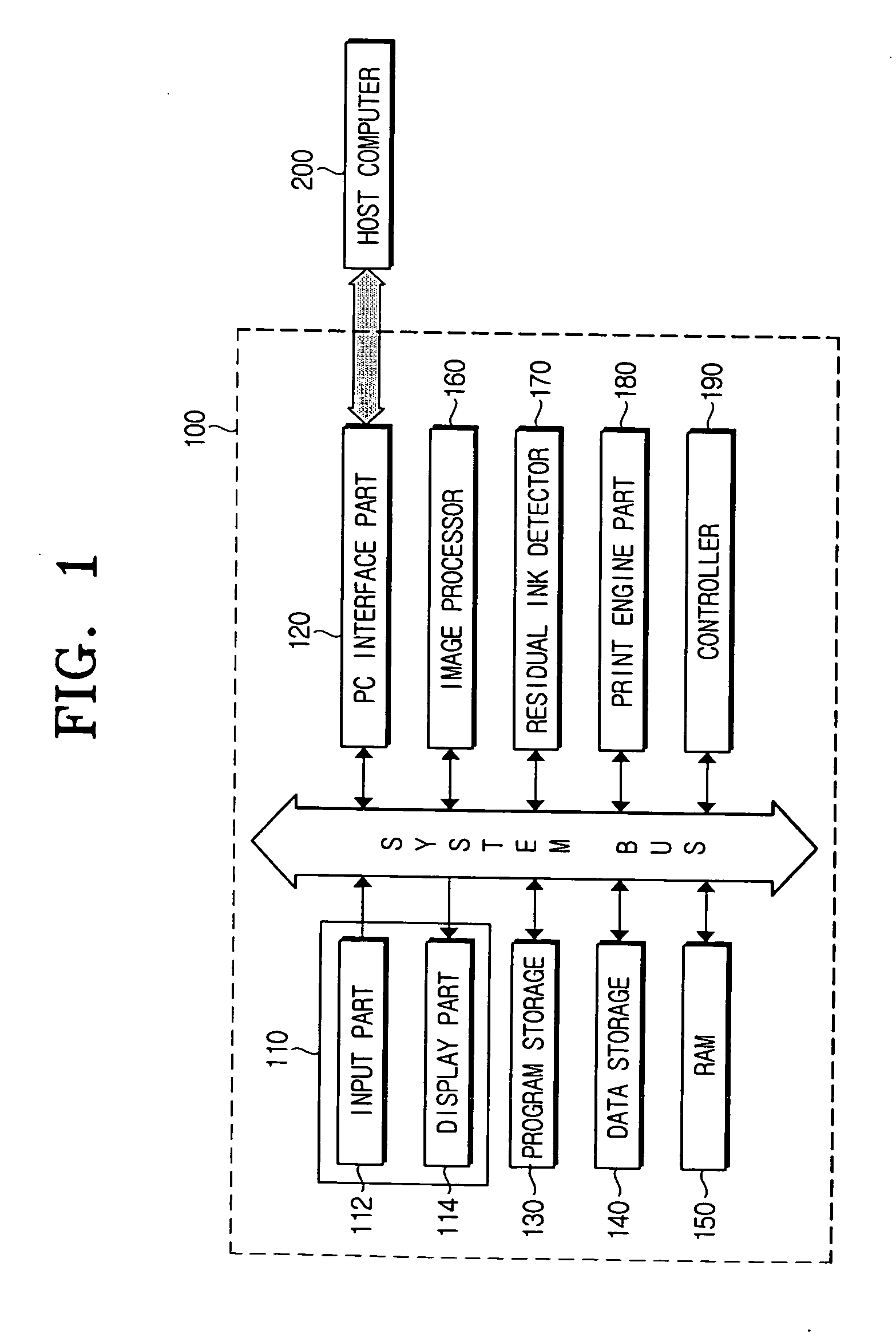
[0033]FIG. 1 is a block diagram of an image forming apparatus, such as an inkjet printer 100, to determine a printing operation depending on a residual developer, such as, ink or toner, according to an embodiment of the present general inventive concept. 100, to determine a printing operation depending on a residual developer, such as, ink or toner, according to an embodiment of the present general inventive concept.

[0034] Referring to FIG. 1, the inkjet printer 100 includes an operation panel 110, a PC interface part 120, a program storage 130, a data storage 140, a random access memory (RAM) 150, an image processor 160, a res...


PUM

PropertyMeasurementUnit
timeaaaaaaaaaa
residualaaaaaaaaaa
poweraaaaaaaaaa

Abstract

A method of controlling an image forming apparatus to determine a printing operation depending on a residual developer includes receiving printing data from an external device, determining whether an auto storage function is set to store the printing data depending on the residual developer, detecting the residual developer in a developing device, comparing the detected residual developer with a predetermined reference residual amount when it is determined that the auto storage function is set, and storing the received printing data in the storage when it is determined that the detected residual developer is less than the reference residual amount according to the comparison. Accordingly, it is possible to prevent deterioration of a print quality due to a lack of the residual developer.

Description

CROSS-REFERENCE TO RELATED APPLICATIONS [0001] This application claims the benefit under 35 U.S.C. § 119(a) from Korean Patent Application No. 2004-27970 filed on Apr. 22, 2004, in the Korean Intellectual Property Office, the entire disclosure of which is incorporated herein by reference. BACKGROUND OF THE INVENTION [0002] 1. Field of the Invention [0003] The present general inventive concept generally relates to a method of controlling a printing operation of an image forming apparatus. More particularly, the present general inventive concept relates to a method of controlling an image forming apparatus, which utilizes toner or ink as a developer, to determine a printing operation of printing data based on a residual developer. [0004] 2. Description of the Related Art [0005] A typical image forming apparatus, such as a photocopier, a printer, a multi-function machine, or a facsimile machine, prints on a printing paper printing data input from an external device (for example, a comp...

Claims


Application Information

Patent Timeline
Patent Type & Authority Applications(United States)
IPC IPC(8): G06K15/00G06F3/12G06K15/02
CPCG06K2215/0085G06K15/02C02F1/24B03D1/1431B03D1/242B01F23/2312B01F23/238
Inventor SEO, JUNG-IL
Owner S PRINTING SOLUTION CO LTD
Learn More