
Reference current generator circuit of organic EL drive circuit, organic EL drive circuit and organic EL display device

Inactive Publication Date: 2005-10-27
ROHM CO LTD
View PDF0 Cites 23 Cited by
  • Summary
  • Abstract
  • Description
  • Claims
  • Application Information

AI Technical Summary

Benefits of technology

[0013] An object of the present invention is to provide a reference current generator circuit of an organic EL drive circuit, which is capable of preventing luminance of an organic EL display device from being changed in a wide operable temperature range of the display device.
[0014] Another object of the present invention is to provide an organic EL element drive circuit capable of keeping white balance of a display device in a wide temperature range and of preventing loss of white balance due to temperature change during use of the display device.
[0017] As mentioned above, in the present invention, the current of the output side transistor of the first current mirror circuit is fed back to the input side transistor thereof through the second current mirror circuit, which is an active load of the first current mirror circuit, so that a current corresponding to a voltage difference between the passive elements having temperature coefficient, which are positive and negative upon temperature change, respectively, is supplied to the output side transistors of the first current mirror circuit through the input side transistor thereof. Thus, it is possible to stably generate a large current having a temperature coefficient, which is determined by a predetermined function reflecting the positive and negative temperature coefficients of the passive elements. The large current reflecting the positive and negative temperature coefficients of the passive elements is derived as the reference current from the output side transistors of the first current mirror circuit.
[0020] Thus, it is possible to obtain, from the reference current having either one of the above mentioned temperature characteristics, the drive current for correcting luminance of the organic EL element in a direction in which luminance of the organic EL element is almost unchanged even when temperature of the display device is changed within a wide range from about −10° C. to about +70° C.
[0021] Particularly, by obtaining respective reference currents having the temperature characteristics for correcting the luminance change with respect to temperature of the organic EL elements for R, G and B colors in directions in which the luminance are not substantially changed by the selection of the operating current ratios, it is possible, in a color display device used in the temperature range from about −10° C. to about +70° C., to prevent white balance on the color display device from being lost.
[0022] As a result, change of luminance of a color display device within the wide temperature range is prevented and white balance of the color display device can be kept unchanged in the wide temperature range within which the color display device is used.

Problems solved by technology

In general, an electronic device, which has an organic EL display device, is operable in a wide temperature range (temperature environment) from −10° C. to +70° C. In such wide operable temperature range of the display device, loss of white balance on a display screen due to environmental temperature change of the electronic device in such temperature range becomes a problem in, particularly, a case where the organic EL display device is a high luminance color organic EL display device.

Method used


Image

  • Reference current generator circuit of organic EL drive circuit, organic EL drive circuit and organic EL display device
  • Reference current generator circuit of organic EL drive circuit, organic EL drive circuit and organic EL display device
  • Reference current generator circuit of organic EL drive circuit, organic EL drive circuit and organic EL display device

Examples


Embodiment Construction

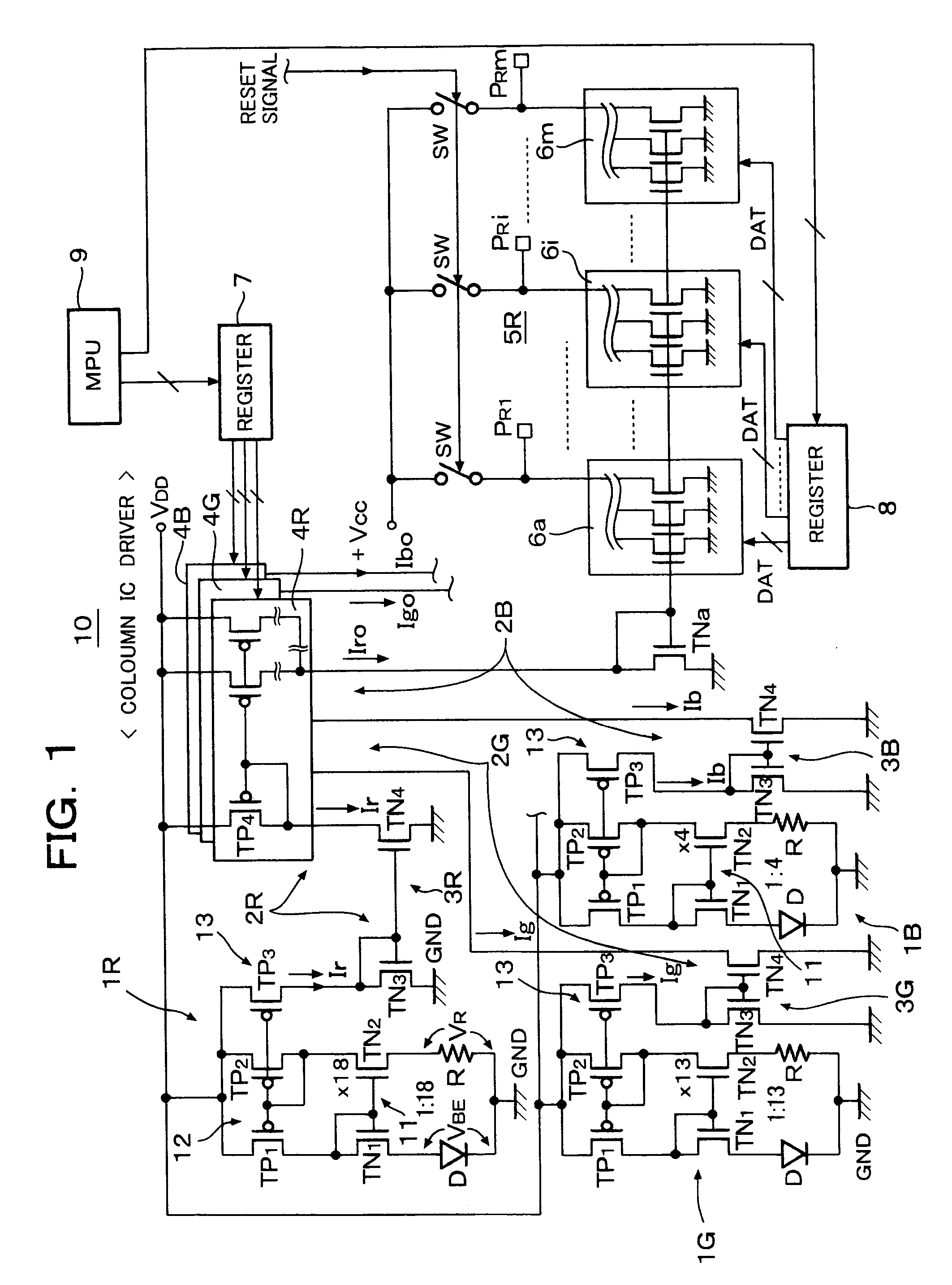
[0026] In FIG. 1, a reference numeral 10 depicts a column IC driver (referred to as “column driver”, hereinafter) as an organic EL drive circuit for driving organic EL elements. The column driver 10 includes a reference current generator circuit 1R corresponding to R (red) color, a reference current generator circuit 1G corresponding to G (green) color and a reference current generator circuit 1B corresponding to B (blue) color. Further, the column driver 10 includes white balance regulator circuits 2R, 2G and 2B for regulating reference currents for respective R, G and B colors of the reference current generator circuits 1R, 1G and 1B.

[0027] The white balance regulator circuit 2R is composed of a current inverter circuit 3R and an 8-bit D / A converter circuit 4R. The white balance regulator circuit 2G is composed of a current inverter circuit 3G and an 8-bit D / A converter circuit 4G and the white balance regulator circuit 2B is composed of a current inverter circuit 3B and an 8-bit...


PUM


Abstract

A first current mirror circuit including an input side transistor, an output transistor and passive elements respectively connected in series with said input side transistor and said output side transistor, temperature coefficients of said passive elements being opposite in characteristics and a second current mirror circuit provided as a load circuit of the first current mirror circuit, for feeding back an output current of the output side transistor to an input of the input side transistor are provided. A drive current is generated on a basis of a current corresponding to a current generated in the output side transistor as a reference current and an operating current ratio of the input side transistor and the output side transistor is selected such that luminance change of organic EL elements with respect to temperature change is restricted.

Description

BACKGROUND OF THE INVENTION [0001] 1. Field of the Invention [0002] The present invention relates to a reference current generator circuit of an organic EL drive circuit, an organic EL drive circuit using the same reference current generator circuit and an organic EL display device using the same organic EL drive circuit. Particularly, the present invention relates to a reference current generator circuit for a display device of an electronic device such as a portable telephone set or a PHS, which is suitable for use in high luminance color display and with which white balance of the display device is unchanged within a wide temperature range by preventing loss of white balance due to change of temperature environment of the display device. [0003] 2. Description of the Related Art [0004] An organic EL display panel of an organic EL display device for use in a portable telephone set, a PHS, a DVD player, PDA (portable digital assistances), etc., including 396 (132×3) terminal pins fo...

Claims


Application Information

Patent Timeline
IPC IPC(8): G09G3/30G09G3/32H05B44/00
CPCG09G3/3208G09G2320/041G09G3/3283G09G3/30G09G3/20
Inventor YAGUMA, HIROSHIFUJISAWA, MASANORIABE, SHINICHI
Owner ROHM CO LTD
Learn More