
Sealing system and method of determining seal integrity

Inactive Publication Date: 2005-10-27
DYNETEK INDS
View PDF9 Cites 16 Cited by
  • Summary
  • Abstract
  • Description
  • Claims
  • Application Information

AI Technical Summary

Benefits of technology

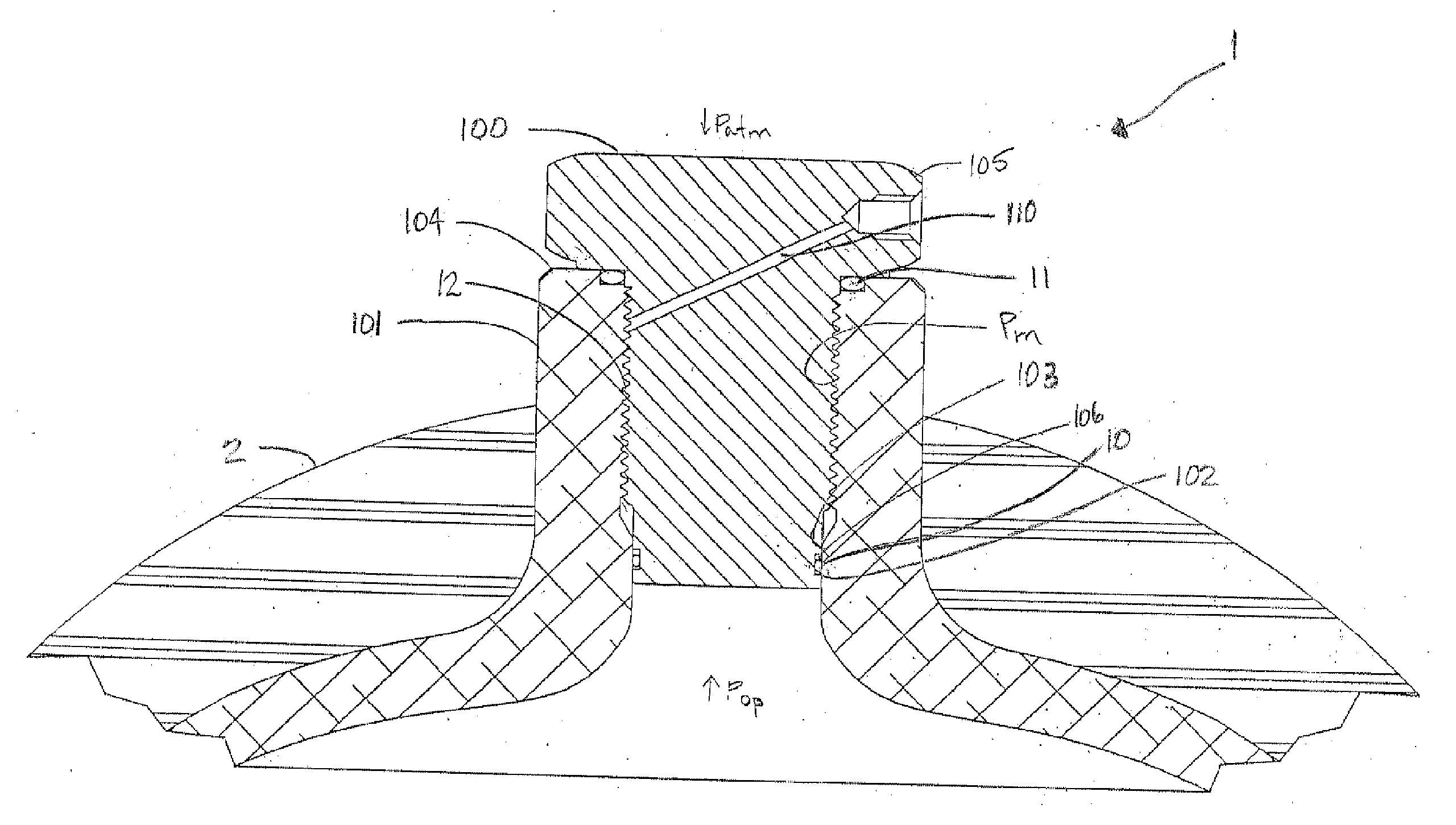
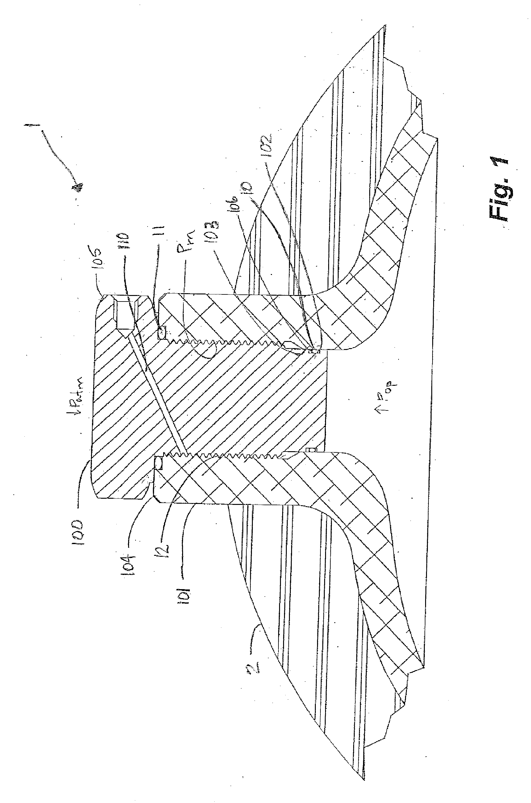
[0009] In one embodiment a unique apparatus, method and system for sealing a high pressure from a lower pressure, such as a high pressure fuel cylinder from atmospheric pressure, utilizes an inner seal spaced from an outer seal by an intermediate space. An intermediate pressure is maintained in the intermediate space to reduce the pressure differential across both the inner seal and the outer seal and thus extend seal life.

Problems solved by technology

Should the seal fail however, the contents of the vessel would be vented to atmosphere causing a loss of fuel from the cylinder and creating a combustion hazard, particularly if the vehicle is in an enclosed structure such as a garage.
Failure of the seal is typically without warning and may result in a situation where a vehicle is stranded without sufficient fuel.
In an incident reported in the media, Toyota recalled a number of fuel cell vehicles as a result of leaking.
Applicant believes that it was determined to be a leak at the valve-cylinder interface and when examined resulted due to failure of an O-ring.
The high pressure differential acts to reduce the life of the seal, despite using highly effective sealing materials.
Further, tapered threads combined with sealing paste or tape has been used to prevent leaking however, Applicant believes this induces additional circumferential stress in the cylinder neck.

Method used


Image

  • Sealing system and method of determining seal integrity
  • Sealing system and method of determining seal integrity
  • Sealing system and method of determining seal integrity

Examples


Embodiment Construction

[0029] Embodiments of the invention are described herein in the context of high pressure cylinders used to fuel vehicles. One of skill in the art would understand that the sealing arrangement described herein is applicable to any situation wherein gases are stored in vessels at high pressure.

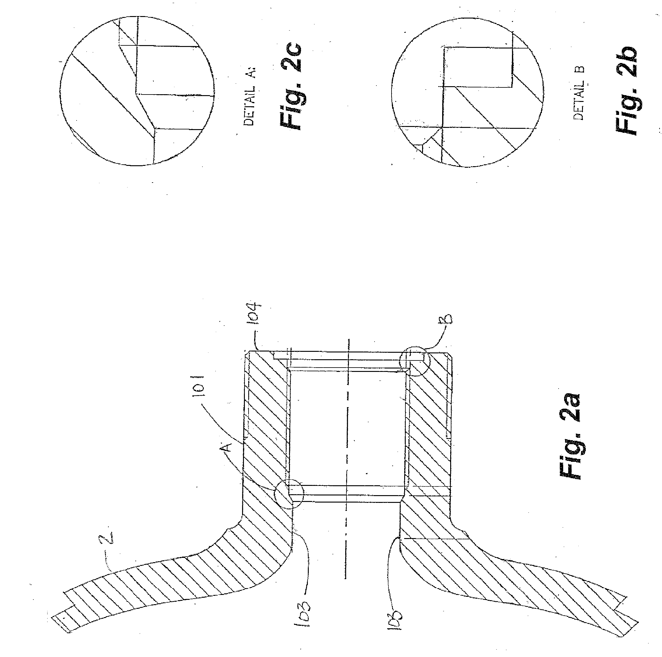
[0030] Having reference to FIGS. 1-5, a system 1 for reliably sealing a high pressure cylinder 2 is shown. The system 1 comprises an inner seal 10, exposed to a first high pressure Pop and an outer seal 11, exposed to a second lower pressure, such as atmospheric pressure Patm, each seal 10,11 being capable of containing the desired operating pressure or first high pressure Pop of the cylinder 2 for a gas of interest, including, but not limited to, compressed natural gas and compressed hydrogen. While discussed herein in the context of separating a high pressure from atmospheric pressure, embodiments of the invention are applicable to any arrangement separating a high pressure from a lower press...


PUM


Abstract

A sealing system for a high pressure fuel cylinder has an inner seal and an outer seal sealing an insert into a boss of the cylinder. Permeation rates as a result of the differential pressures across the seals are balanced across both the inner and outer seals to maintain a constant pressure in an intermediate space between the seals. Permeation is balanced by selecting suitable seal materials or by seal geometry or by providing a pressure relief device to the intermediate space to release excess pressure built up in the intermediate space beyond a desired intermediate pressure. Maintaining the intermediate pressure lower than the cylinder pressure and higher than atmospheric pressure results in lower pressure differentials across the seals, extending the seal life. A pressure switch or gauge is provided to monitor the pressure in the intermediate space. Changes in the pressure are indicative of a leak in one or both of the seals.

Description

CROSS REFERENCE TO RELATED APPLICATION [0001] This application is a regular application claiming priority of U.S. Provisional Patent application Ser. No. 60 / 564,605 filed on Apr. 23, 2004, the entirety of which is incorporated herein by reference.FIELD OF THE INVENTION [0002] Embodiments of the invention relate to sealing systems for pressure vessels and more particularly, to sealing systems for high pressure fuel cylinders and additionally, incorporating means for maintaining and monitoring seal integrity. BACKGROUND OF THE INVENTION [0003] High pressure cylinders are known typically for carrying and supplying alternative fuels to vehicles such as compressed natural gas (CNG) vehicles and for hydrogen fuel cells. Due to the rigid safety requirements for such vessels, it is desirable to provide systems for sealing the boss or neck of the vessel that are robust and capable of maintaining the high pressure in the cylinders without fear of leaking. [0004] Typically, conventional cylind...

Claims


Application Information

Patent Timeline
IPC IPC(8): F16J12/00F16J13/12F16J15/00F16J15/02F17C13/02F17C13/06
CPCF16J13/12F16J15/006F17C13/06F17C2205/0305F17C2201/0104F17C2201/056Y02E60/321F17C2221/033F17C2223/0123F17C2223/036F17C2250/043F17C2260/038F17C2270/0168F17C2221/012Y02E60/32
Inventor JUPP, DAVID J.
Owner DYNETEK INDS
Learn More