
Restricted scan reordering technique to enhance delay fault coverage

a delay fault and scan reordering technology, applied in the field oflogic delay testing, can solve the problems of correlation between the pair and the device/or wiring propagation delay exceeding specified limits, the logic to malfunction at desired clock rate, and the correlation between the pair may create untestable delay faults, etc., to achieve the effect of increasing the chip area, enhancing the delay fault coverage, and avoiding increasing routing overhead

Inactive Publication Date: 2005-10-20
NEC CORP
View PDF2 Cites 10 Cited by
  • Summary
  • Abstract
  • Description
  • Claims
  • Application Information

AI Technical Summary

Benefits of technology

[0008] Unlike other solutions, the present invention can enhance delay fault coverage by rearranging scan flip-flops without increasing routing overhead, which may result in routing congestion or increase in chip area. In addition, the present invention takes advantage of using the circuit function rather than topology while still achieving reasonable CPU times.

Problems solved by technology

Failures that cause logic to malfunction at desired clock rates are referred to as delay faults.
These delay faults, particularly those occurring within integrated circuits, are typically due to random variations in process parameters that may cause device and / or wiring propagation delays to exceed specified limits.
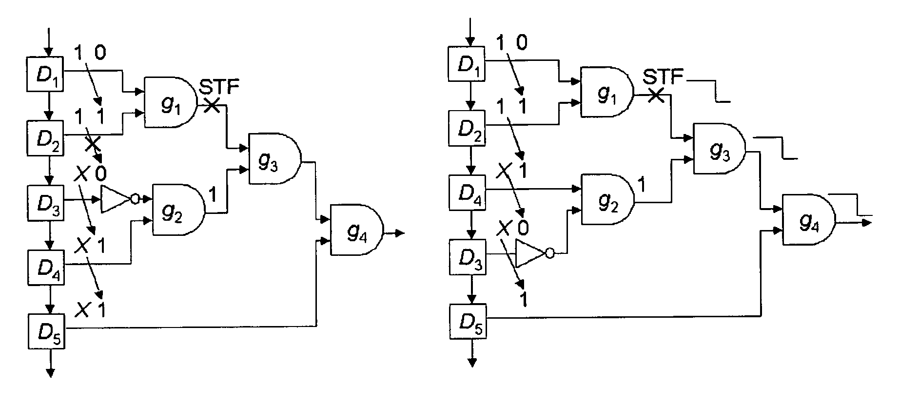
If a pair of adjacent flip-flops drive the same fanout cone, then the correlation between the pair may create untestable delay faults.
This, unfortunately, requires prohibitive CPU time and is not practical for large circuits that have a million or more gates.

Method used


Image

  • Restricted scan reordering technique to enhance delay fault coverage
  • Restricted scan reordering technique to enhance delay fault coverage
  • Restricted scan reordering technique to enhance delay fault coverage

Examples


Embodiment Construction

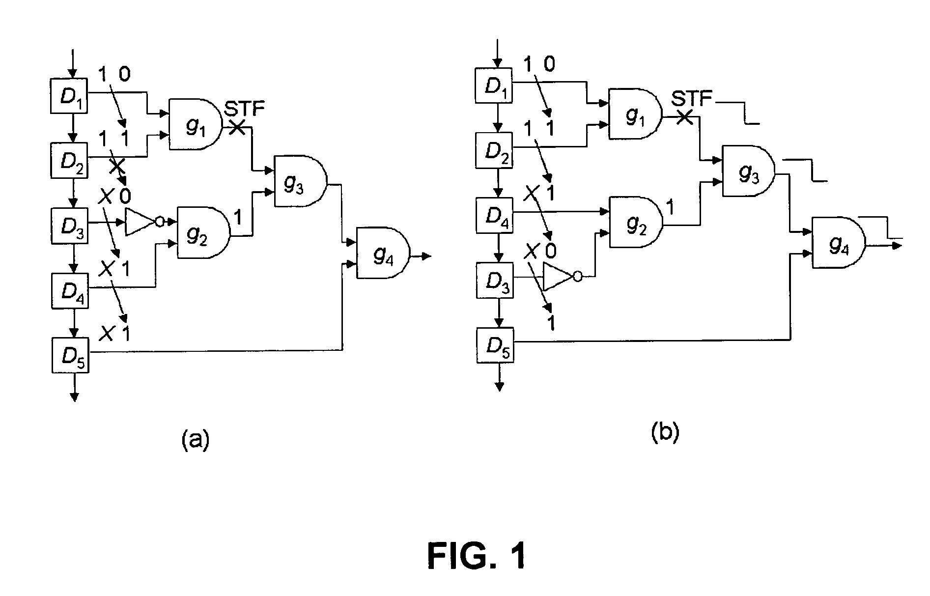
[0016] The number of distinct pattern pairs that can be applied using the skewed load approach is 2(2n−1) compared to 2n(2n−1) that can be applied by enhanced scan, where n is the number of scan inputs of the circuit under test. Hence, some transition delay faults that are detectable in an enhanced scan environment are undetectable when the skewed-load approach is used due to shift dependency. The faults that are undetectable by using the skewed-load approach but detectable under an enhanced scan environment are referred to herein as “shift dependency undetectable faults.”

[0017]FIG. 1A shows an example of a shift dependency undetectable fault. The STF fault in the circuit shown in FIG. 1A is untestable under a standard scan environment when the skewed-load approach is used. In order to initialize the STF fault, both D1 and D2 should be assigned 1's at an initialization cycle. The 1 at D2 at the initialization cycle shifts to D3 at the next cycle (launch cycle). However, in order to ...


PUM


Abstract

The present invention is directed to improved delay fault testing by optimizing the order of scan cells in a scan chain.

Description

[0001] This Utility Patent Application is a Non-Provisional of and claims the benefit of U.S. Provisional Patent Application Ser. No. 60 / 563,679 filed on Apr. 20, 2004, the contents of which are incorporated by reference hereinBACKGROUND OF THE INVENTION [0002] The present invention is related to logic delay testing, in particular in the context of logic circuit designs. [0003] Ascertaining the correct operation of digital logic circuits requires verification of functional behavior as well as correct operation at desired clock rates. Failures that cause logic to malfunction at desired clock rates are referred to as delay faults. These delay faults, particularly those occurring within integrated circuits, are typically due to random variations in process parameters that may cause device and / or wiring propagation delays to exceed specified limits. The detection of a delay fault normally requires application of a two-pattern test: a first pattern that initializes the targeted faulty ci...

Claims


Application Information

Patent Timeline
Patent Type & Authority Applications(United States)
IPC IPC(8): G01R31/28G01R31/3185G06F17/50
CPCG01R31/318544
Inventor WANG, SEONGMOONLI, WEICHAKRADHAR, SRIMAT T.
Owner NEC CORP
Learn More