
Thermostat for water boiler

a technology for water boilers and thermostats, which is applied in the direction of fluid heaters, electrical appliances, lighting and heating apparatus, etc., can solve the problems of thermostat failure, boilers fitted with a faulty thermostat either not operating at all or permanently connected, and the boiler fitted with a faulty thermostat can not operate at all

Inactive Publication Date: 2005-10-20
THERMION
View PDF4 Cites 9 Cited by
  • Summary
  • Abstract
  • Description
  • Claims
  • Application Information

AI Technical Summary

Benefits of technology

[0018] Bearing in mind this state of the art, it is one of the objects of the present invention to provide a thermostat with an improved heat limitation arrangement primarily intended to prevent overheating in hot water tanks even following failure of the prior-art bimetal thermostat commonly used at present.
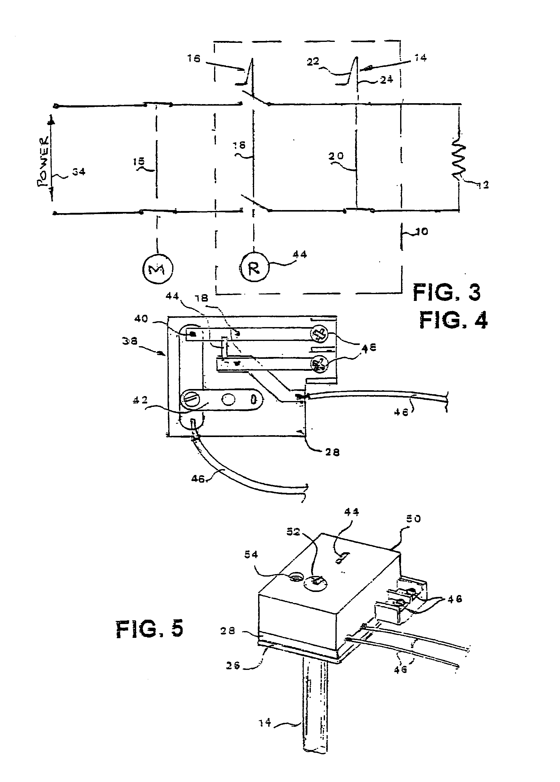
[0028] At least one of the switches shown in FIGS. 1 and 3 are two-pole switch which has some safety advantages, but It is of course feasible, and less costly, to effect the same result using single pole switches.

Problems solved by technology

In hot water boilers when electric power applied is not properly controlled, the heater element can generate high or even dangerous steam pressure, aside from wasting much electricity and possibly burning out the element itself.
A boiler fitted with a faulty thermostat either will not operate at all or will leave the current permanently connected.
One known type of thermostat failure occurs when the switch contacts become welded or stuck together, whereafter the thermostat is no longer responsive to high water temperature.
Unfortunately most hot water thermostats are located in a position where check-up for proper functioning is most unlikely to be carried out—such locations including roofs and storage lofts.
Modern boilers are well protected against explosion, but thermostat failure which does occur can have unpleasant consequences, for example causing a failure to provide hot water needed when needed, and more seriously causing a person showering to be scalded by 90° C. water, or less seriously failing to heat water required for washing, showering or bathing.

Method used


Image

  • Thermostat for water boiler
  • Thermostat for water boiler
  • Thermostat for water boiler

Examples


Embodiment Construction

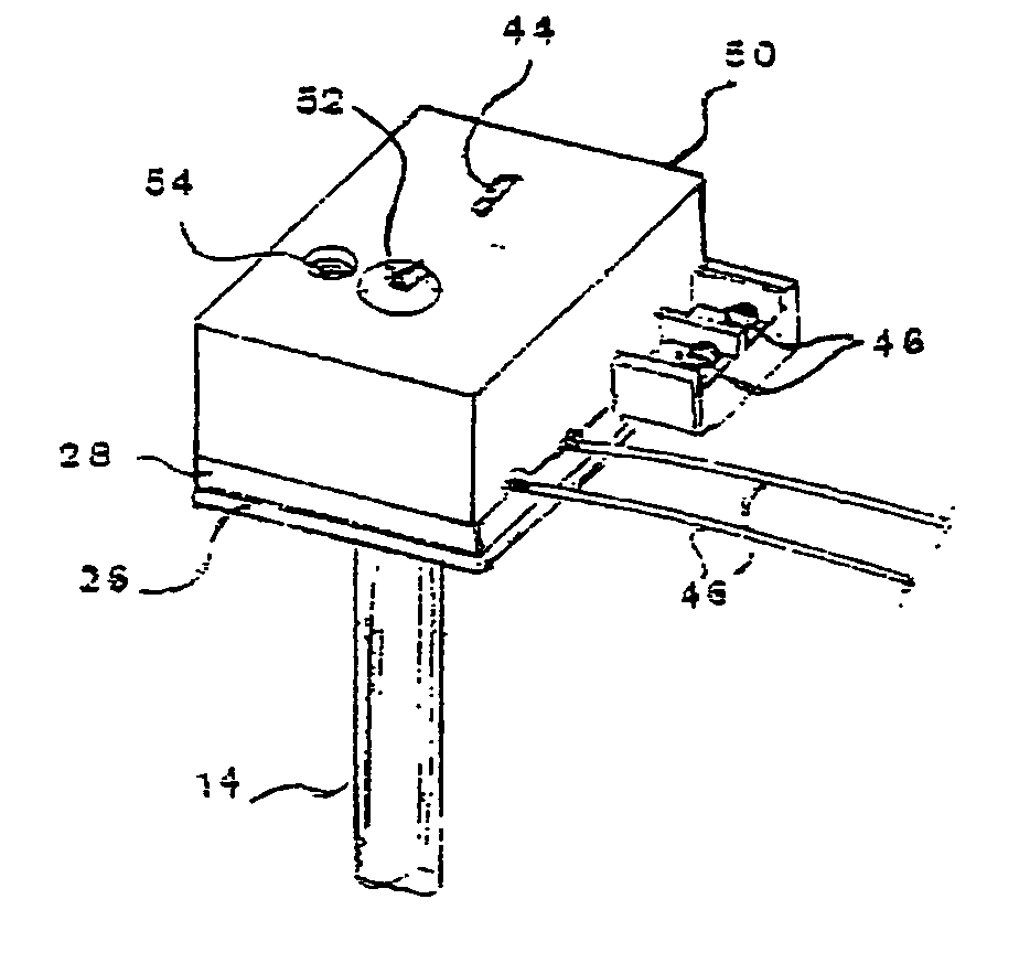
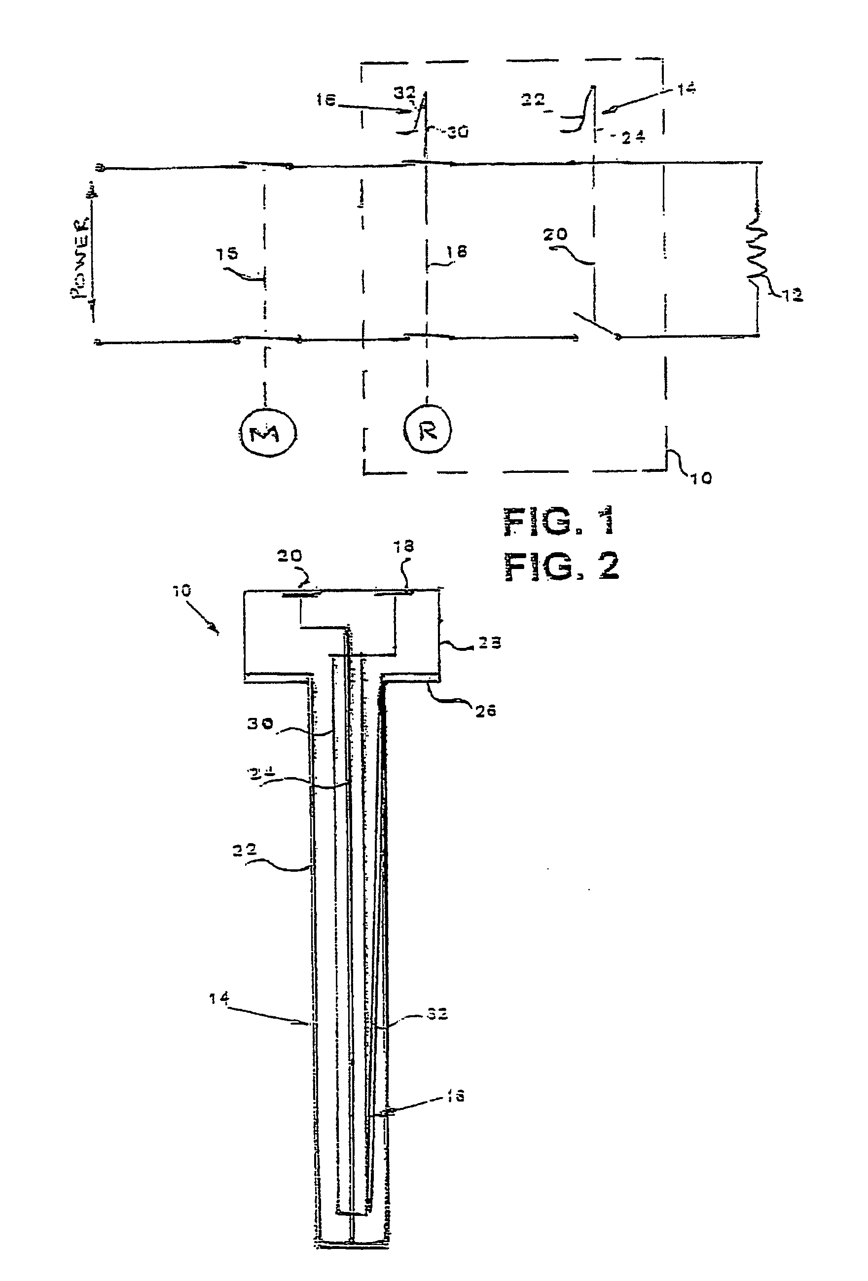
[0037] There is seen in FIG. 1 an electrical diagram representing the improved thermostat 10 for control of power to the heating element 12 of an electric hot water boiler, the diagram showing the improvement of the invention, comprising the addition to the extended length first bimetal device 14 of a second bimetal device 16, and the addition of a second switch 18 to the first switch 20.

[0038] The first bimetal device 14 is arranged for thermal at least indirect contact with water being heated. The device 14 could be directly immersed in the water being heated, but current practice is to insert the bimetal device into a steel tube (not shown) which is immersed in the water. This arrangement eases servicing of the thermostat at the cost of some loss in accuracy.

[0039] To complete the diagram there is also shown in the figure the standard manually-operated user control switch 15.

[0040] With reference to the rest of the figures, similar reference numerals have been used to identify...


PUM


Abstract

A thermal control device (10) for electrically powered appliances, in particular a thermostat to protect against overheating of a hot water boiler. The thermostat having a structure (26) supporting a first (20) and second (18) electric switches disposed in series between an electric power supply and an electric heating element, an extended length first bimetal device (14) being arranged for thermal at least indirect contact with water being heated, a second bimetal device (16) disposed inside the first bimetal device and acting to open the second switch if the second bimetal device reaches a second temperature higher than a first temperature due to the failure of the first bimetal device to open the first switch.

Description

FIELD AND BACKGOUND OF THE INVENTION [0001] The present invention relates to the thermal control of electrically powered appliances. More particularly, the invention provides a thermostat which improves security against overheating of a hot water boiler. [0002] Thermostats are automatic control devices that switch electric power on / off with relation to the temperature of the material being controlled. These devices have been in widespread use for many decades in air conditioning, hot water boilers and in control of thermal industrial processes. [0003] In hot water boilers when electric power applied is not properly controlled, the heater element can generate high or even dangerous steam pressure, aside from wasting much electricity and possibly burning out the element itself. Without a properly functioning thermostat, power could be connected for a long period to the heater element, and would not be switched off when water reaches a required temperature, for example about 60°-70° C....

Claims


Application Information

Patent Timeline
IPC IPC(8): F24H9/20H05B1/02
CPCH05B1/0216F24H9/2021
Inventor MAGAL, YOSEF
Owner THERMION
Learn More